Perfect Harmony GENIII/e User’s Manual Hardware Components
A1A19000405A: Version 1.3 2-3
2
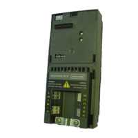
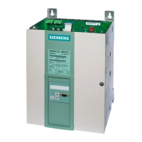
Figure 2-2: Typical GENIII/e style VFDs
2.1.1 Transformer Section
The Transformer Section of the Perfect Harmony drive contains the input power transformer. Input power wires enter
the drive through this section and output wires to the motor exit the drive through this section. The input and output
power wiring can enter and exit the drive from either the top or bottom of this section. In addition to the main multi-
secondary phase-shifting power transformer, the transformer section contains either one or more blowers (at the top
of the cabinet) used to cool the drive. Refer to Figure
2-3. Major components of the Transformer Section are
illustrated in Figure 2-3 and described in Table 2-1.
*
Note: Input and output wiring enters the cabinet from the top or bottom of the transformer section.

 Loading...


