Fail-Safe Modules
7.6 EM 4 F-DI/3 F-DO DC24V PROFIsafe digital electronic module
ET 200S Distributed I/O System - Fail-Safe Modules
156 Installation and Operating Manual, 08/2008, A5E00103686-07
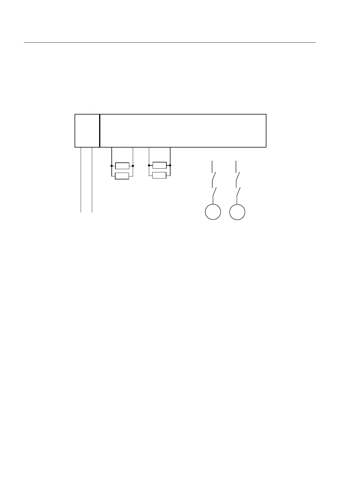
Application 3: Wiring Two Loads in Parallel to each Digital Output
Avoiding/Managing Cross-Circuits:
To protect against cross circuits between P and M-switches in fail-safe digital outputs, we
recommend the following wiring scheme:
/ 0
'2
0
'2
3
'2
0
'2
3
'2
0
'2
3
/ 0
.
.
.
.
0
0
.
.
.
.
4 F-DI/3 F-DO
PM-E
Figure 7-46 Diagram of Two Relays Wired in Parallel to 1 F-DO of EM 4 F-DI/3 F-DO DC24V
7.6.7 Diagnostic functions of EM 4 F-DI/3 F-DO DC24V PROFIsafe
Behavior in Case of Supply Voltage Failure
Failure of the Vs sensor power supply of the EM 4 F-DI/3 F-DO DC24V PROFIsafe is
indicated by the VsF LED on the F-module. This information is also provided in the module
(diagnostic entry). Either all channels of the module are passivated or, in the case of
channel-specific passivation, the relevant channels are passivated.
In the case of a voltage dip in the external auxiliary voltage, the SF LED lights up, the
module is passivated.
With the subsequent supply recovery (level must remain above the specified value for at
least 1 minute (refer to the technical specifications: voltages, currents, electrical potentials))
the SF LED goes out again, the module remains passivated. The SF LED flashes if there are
no other errors, until the error is acknowledged.
 Loading...
