Fail-Safe Modules
7.3 PM-E F pp DC24V PROFIsafe power module
ET 200S Distributed I/O System - Fail-Safe Modules
88 Installation and Operating Manual, 08/2008, A5E00103686-07
Terminal Designation
11 P
12 M
Terminals (relay contacts) for fail-safe switching of voltage bus P2
15 P
16 M
Terminals (relay contacts) for fail-safe switching of voltage bus P2
CAUTION
If high currents can occur on P and M, you must wire terminals 11 and 15 (P) and 12 and
16 (M) in parallel.
Otherwise, high current loads may cause the terminals to heat up.
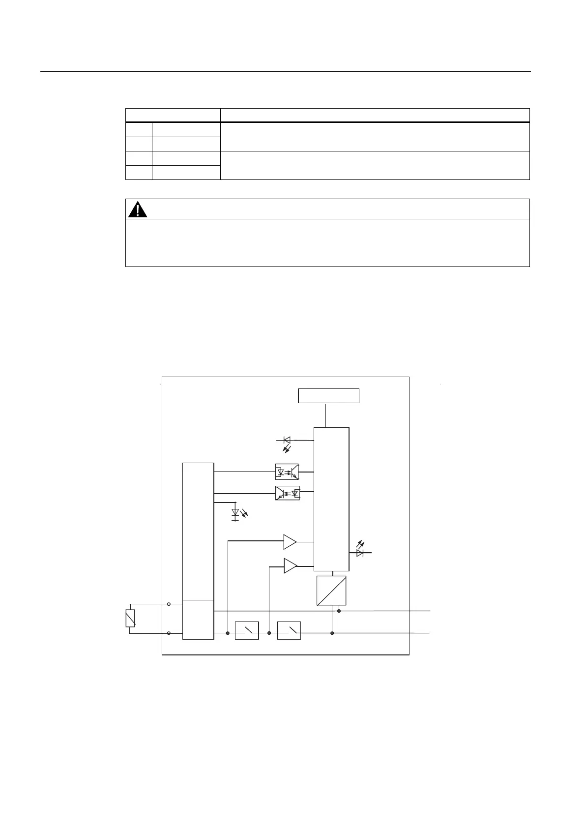
7.3.3 Wiring of the PM-E F pp DC24V PROFIsafe
Block Diagram
9
0
6)
0
3
0
0
3:5
9
3
3
$GGUHVVVZLWFK
3URFHVVLQJORJLF
%DFNSODQHEXVLQWHUIDFH
5HDGEDFN
5HOD\ 5HOD\
6WDWXVRI
RXWSXW
Figure 7-11 Block diagram of the PM-E F pp DC24V PROFIsafe
 Loading...
