ET 200S Distributed I/O System - Fail-Safe Modules
Installation and Operating Manual, 08/2008, A5E00103686-07
27
Address Assignment and Installation
3
3.1 Address assignments in the F-CPU
Address Assignment
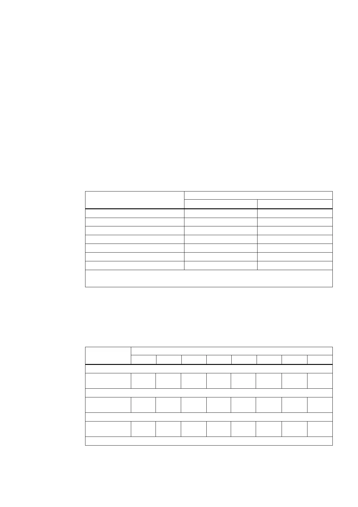
The fail-safe modules occupy the following address ranges in the F-CPU:
● For S7 Distributed Safety: in the area of the process image
● For S7 F/FH systems: in the area of the process image
Table 3- 1 Address Assignment in the F-CPU
Occupied Bytes in the F-CPU:
F-Module
In Input Range In Output Range
PM-E F pm DC24V PROFIsafe x + 0 to x + 4 x + 0 up to x + 4
PM-E F pp DC24V PROFIsafe x + 0 up to x + 4 x + 0 up to x + 4
PM-D F DC24V PROFIsafe x + 0 up to x + 4 x + 0 up to x + 4
4/8 F-DI DC24V PROFIsafe x + 0 to x + 5 x + 0 to x + 3
4 F-DI/3 F-DO DC24V PROFIsafe x + 0 up to x + 6 x + 0 up to x + 4
4 F-DO DC24V/2A PROFIsafe x + 0 up to x + 4 x + 0 up to x + 4
1 F-RO DC24V/AC24..230V/5A x.0 and x.1* —
x = Module start address
* The bit addresses can be moved using the "Pack addresses" function.
Addresses Occupied by Useful Data
The useful data occupy the following addresses of the assigned addresses of the fail-safe
modules in the F-CPU:
Table 3- 2 Addresses Occupied by Useful Data
Occupied Bits in F-CPU per F-Module:
Byte in the
F-CPU
7 6 5 4 3 2 1 0
PM-E F pm DC24V PROFIsafe:
x + 0 — — — — — Channel
2
Channel
1
Channel
0
PM-E F pp DC24V PROFIsafe:
x + 0 — — — — — — — Channel
0
PM-D F DC24V PROFIsafe:
x + 0 — — Channel
5
Channel
4
Channel
3
Channel
2
Channel
1
Channel
0
4/8 F-DI DC24V PROFIsafe:
 Loading...
