Fail-Safe Modules
7.7 4 F-DO DC24V/2A PROFIsafe digital electronic module
ET 200S Distributed I/O System - Fail-Safe Modules
168 Installation and Operating Manual, 08/2008, A5E00103686-07
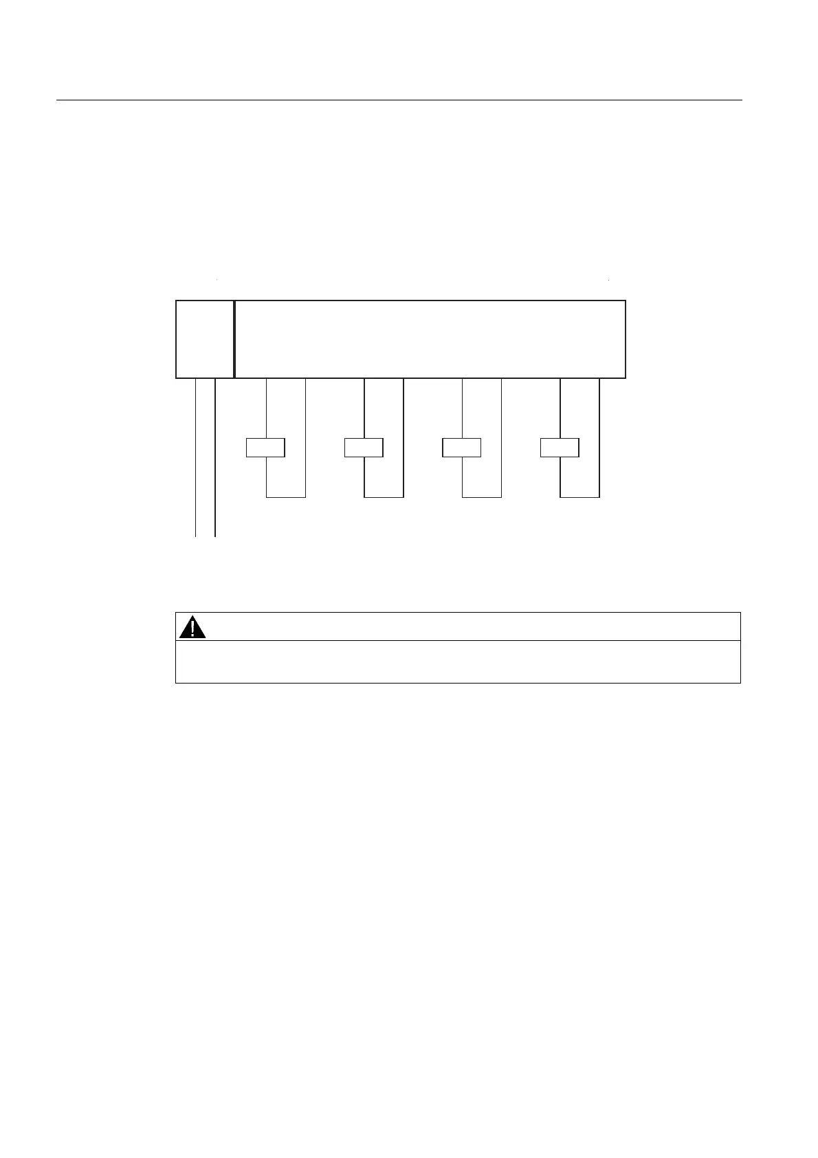
Application 1: Wiring a load to each digital output
Each of the four fail-safe digital outputs consists of a DOx P P-switch and a DOx M M-switch.
You connect the load between the P and M-switches. The two switches are always activated
so that voltage is applied to the load. This configuration achieves safety class SIL3/Category
4/PLe.
The wiring is carried out on an appropriate terminal module.
30(
/ 0
/ 0
'2
0
'2
3
'2
0
'2
3
. .
'2
0
'2
3
.
'2
0
'2
3
.
)'2
Figure 7-51 Wiring diagram of the EM 4 F-DO DC24V/2A PROFIsafe
WARNING
In order to achieve SIL3/Category 4/PLe with this wiring, you must install a suitably-
qualified sensor, for example in accordance with IEC 60947.
 Loading...
