Fail-Safe Modules
7.8 1 F-RO DC24V/AC24..230V/5A Digital Electronic Module
ET 200S Distributed I/O System - Fail-Safe Modules
Installation and Operating Manual, 08/2008, A5E00103686-07
183
Wiring the Load Voltage and the Load
The connections of the relay output features electrically isolated NO contacts. This means
that power must be fed to these contacts from an external source. Connect the load supply
(supply 1) and the load (load 1) in series to the connections OUT 1
(terminals 9;13)/(terminals 10;14). This circuit ensures that the NO contacts of the relay
reliably cut off power to the load voltage supply. This redundant series circuit of the relay
contacts allows shutdown if one of the two relays fails.
The two circuits are not electrically interdependent. They are logically interconnected by way
of common control. This means that the potential in the OUT 2 (terminals 11;15)/(terminals
12;16), supply 2 and load 2 electric circuit may be different.
WARNING
If you have connected extra low voltage (SELV/PELV) to one channel, then the other
channel of the F-RO module must also be connected to extra low voltage.
Information on the F-RO module and the current TÜV certificate report are available for
download on the Internet from http://support.automation.siemens.com, "Product Support"
pages.
Reading back the relay contacts
Always compare the readback value returned from the F-RO module with the control status
in the safety program. The S7 Distributed Safety F-systems provide an F-application block
FB 216 "F_FDBACK" for this purpose: You can use the "Feedback circuit monitoring" in your
safety program (see the
S7 Distributed Safety, Configuring and Programming)
manual.
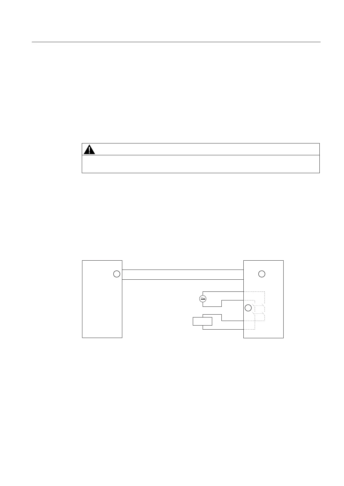
)'2 3
0
)52
$FWXDWRU
① F-RO with Integrated FEEDBACK input
② Relay contacts for switching the load
③ Output Q
Figure 7-58 Example of an interconnection with F-application block FB 216
 Loading...
