Fail-Safe Modules
7.8 1 F-RO DC24V/AC24..230V/5A Digital Electronic Module
ET 200S Distributed I/O System - Fail-Safe Modules
Installation and Operating Manual, 08/2008, A5E00103686-07
185
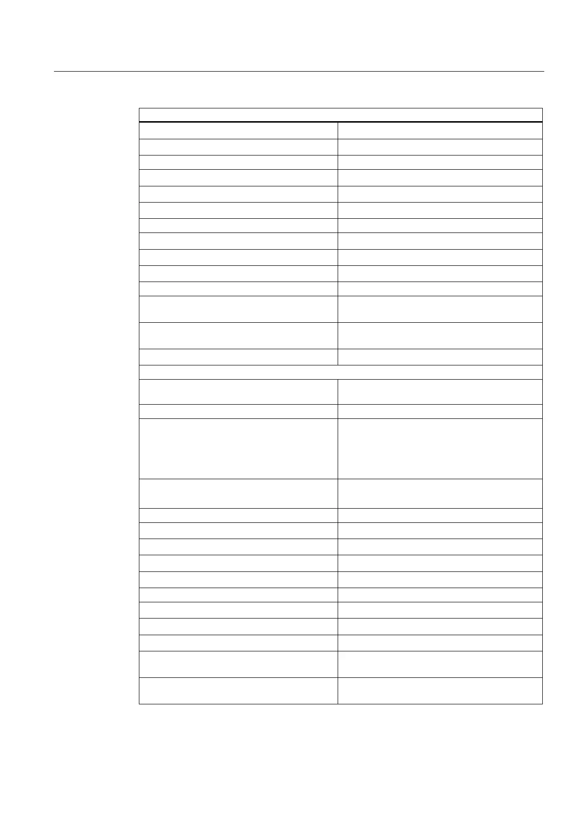
Technical Specifications
• In the I/O area for inputs
2 bits
• In the I/O area for outputs
--
Length of cable
• Unshielded for load contact
200 m, maximum
• Shielded for load contact
200 m, maximum
• Control cable (input)
10 m, maximum
Maximum achievable safety class
• In accordance with IEC 61508
SIL3
• In accordance with EN 954
Category 4
• In accordance with ISO 13849
PLe
Fail-safe performance characteristics SIL3
• Low demand mode (average probability of
failure on demand)
< 1.00E-05
• High demand/continuous mode (probability of
a dangerous failure per hour)
< 1.00E-09
• Acceptance ID
cULus, CE, C-Tick
Voltages, Currents, Potentials
Control voltage 20.4 to 28.8 VDC (supplied from fail-safe output of
an F-DO)
Total current at both channels
• Horizontal installation
– Up to 40 °C
– Up to 50 °C
– Up to 60 °C
8 A
6 A
5 A at max. control voltage 24.8 VDC
3 A at max. control voltage 28.8 VDC
• Vertical installation
– Up to 40 °C
6 A
Electrical isolation
• Between channels and backplane bus
Yes
• Between channels and control voltage
Yes
• Between channels
Yes
• Between channels/control voltage and shield
Yes
Permissible potential difference between
• Shield and ET 200S bus connection
75 VDC/60 VAC
• Control voltage and shield
75 VDC/60 VAC
• ET 200S bus connection and control voltage
75 VDC/60 VAC
• Channel 1 and shield, ET 200S bus
connection, control voltage, channel 2
250 VAC
• Channel 2 and shield, ET 200S bus
connection, control voltage, channel 1
250 VAC
 Loading...
