Fail-Safe Modules
7.2 PM-E F pm DC24V PROFIsafe Power Module
ET 200S Distributed I/O System - Fail-Safe Modules
72 Installation and Operating Manual, 08/2008, A5E00103686-07
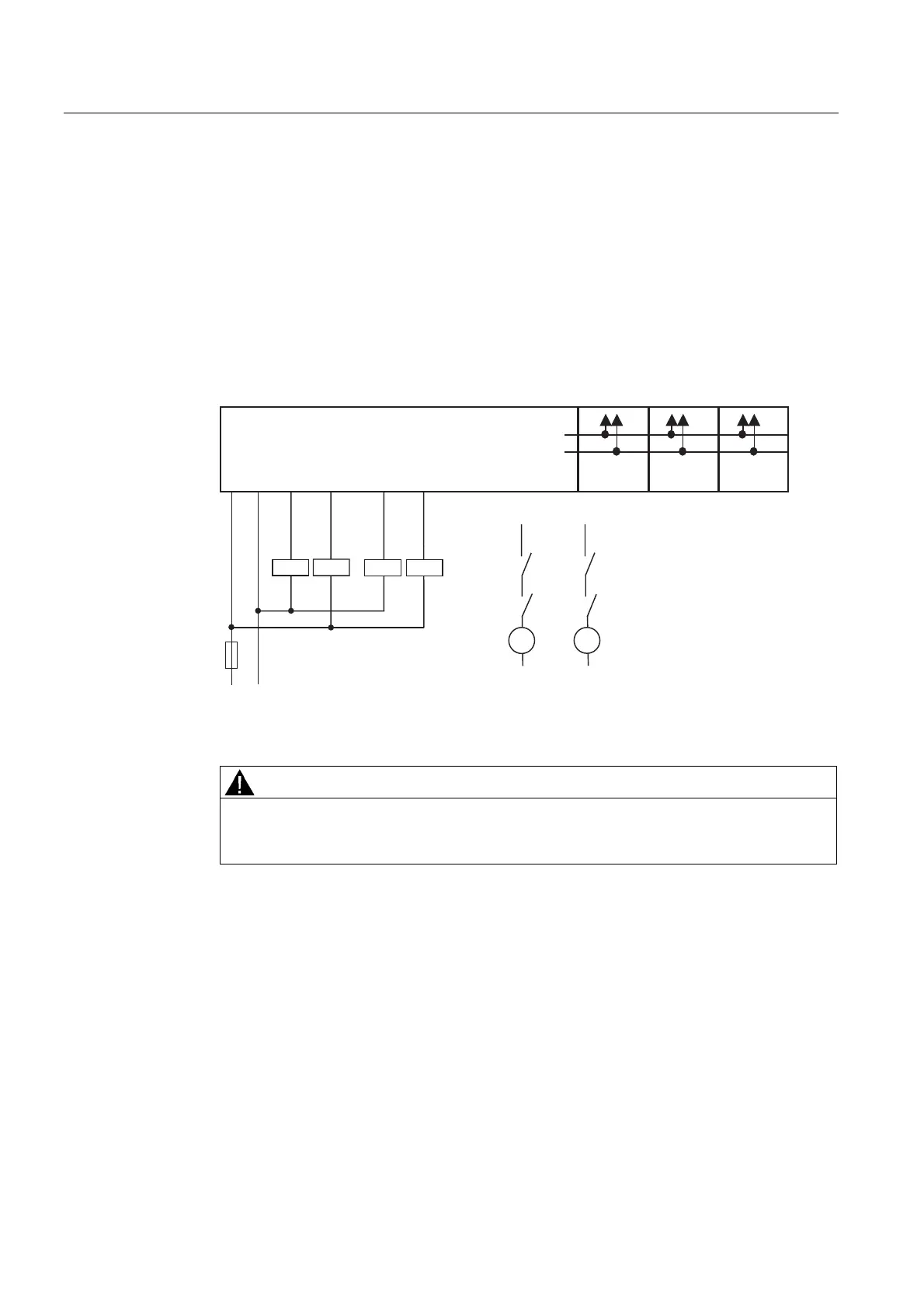
Application 2: Wiring loads to L+ and M at each digital output
You can connect two relays using one fail-safe digital output. The following conditions should
be kept in mind:
● L+ and M of the relays must be connected with L+ and M of the PM-E F pm (reference
potential must be equal).
● The normally open contacts of the two relays must be connected in series.
This connection can only be made on digital outputs DO 0 and DO 1 (not DO 2). With this
circuit, you achieve:
● SIL3/Category 4/PLe
30()SP'&9
/ 0
/ 0
'2
0
'2
3
'2
0
'2
3
30
33
(0'2 (0'2 (0'2
.
. . . .
.
.
.
0
0
3
'2
3
3
'2
0
'2
3
'2
0
'2
3
'2
0
'2
3
'2
0
Figure 7-7 Wiring diagram for each of two relays on DO 0 and DO 1 of the PM-E F pm DC24V
PROFIsafe
WARNING
When connecting two relays on one digital output (as shown in the figure above), the
errors "wire break" and "overload" are detected only at the P-switch of the output (not at
the M-switch).
 Loading...
