--_b
17 | 52
An electric heater must always be protected by a safety limit thermostat!
4.3.4 4-pipe fan coil unit
Heating and cooling
In 4-pipe applications, the thermostat controls two valves in heating and
cooling mode. 4-pipe application is the default setting for parameter P01 (P01
= 03).
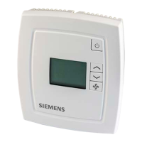
The diagrams below show the control sequence for 2-position control.
On/Off control
]
Room temperature setpoint
Control command 'Valve' (H)
Control command 'Valve' (C)
d
Dead zone (dead band) (P08)
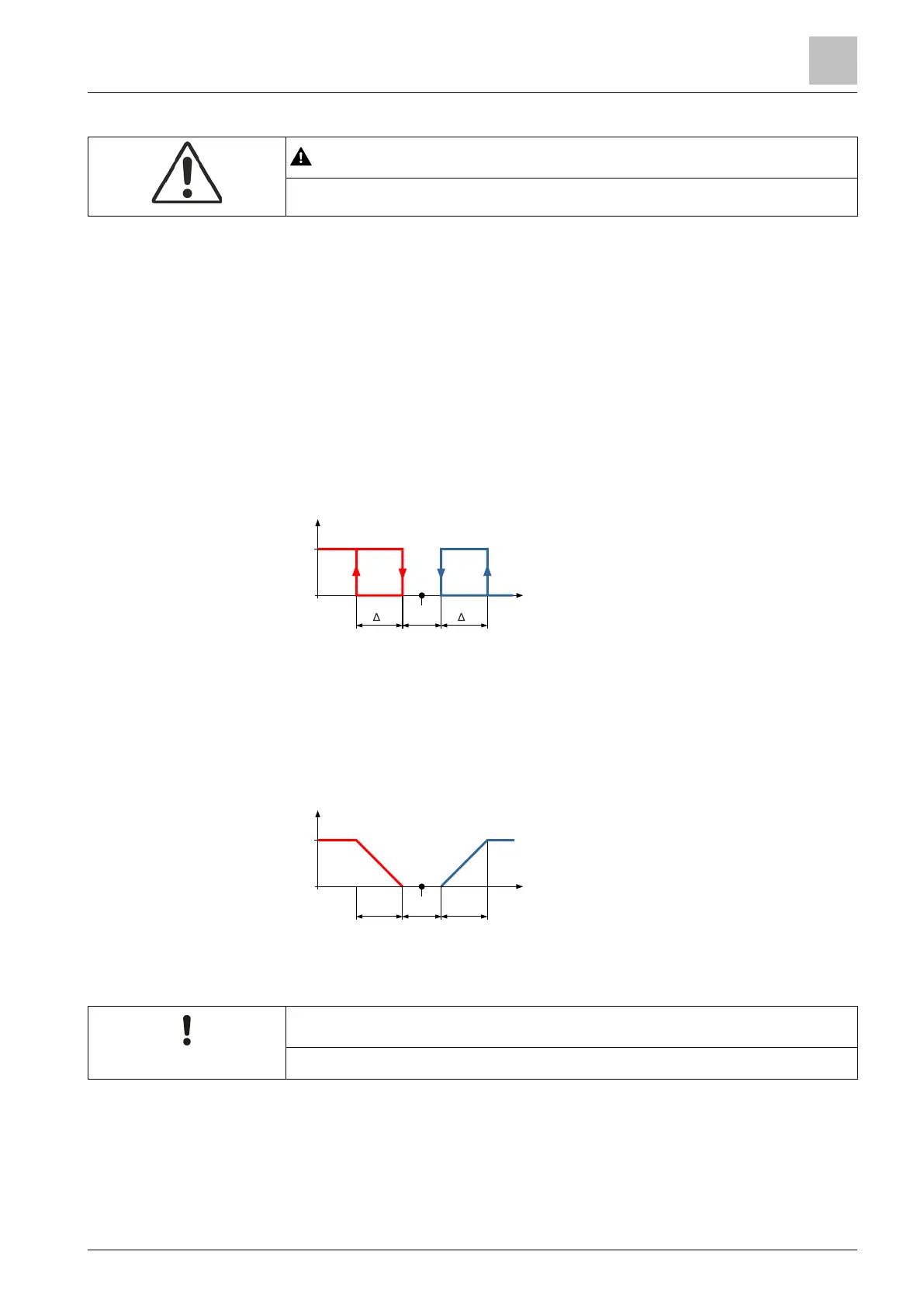
Modulating control
PWM, DC 0…10 V or 3-position
]
Room temperature setpoint
Control command 'Valve' (H)
Control command 'Valve' (C)
d
Dead zone (dead band) (P08)
The diagrams only show the PI proportional part of the thermostat.
For detailed information about setting the sequence and the control outputs
refer to chapters 'Applications [➙ 11]', 'Setpoint and sequences [➙ 18]' and
'Control outputs [➙ 20]'.
V1
100
0
Y [%]
w
T [°C]
V2
X
DZ
X
P
X
P
 Loading...