| 52
A6V11917618_en--_b
10 Connection diagrams
2-pipe / heating or cooling
– On/Off or PWM
2-pipe / heating or cooling
– DC valve
2-pipe / heating or cooling
– 3-position
● DO4 = Open
● DO5 = Close
2-pipe with el. heater / heating
or cooling
– On/Off or PWM and el. heater
230 V
2-pipe with el. heater / heating
or cooling
– DC 0…10 V and el. heater
230 V
– On/Off or PWM
● V1 = Heating
● V2 = Cooling
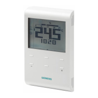
N1 Room thermostat RDB160BN S1, S3 Switch (keycard, window contact, presence detector)
M1 Fan (1-/ 2-/ 3- speed or DC 0…10 V) B1, B2 Temperature sensor (return air temperature, external
room temperature, changeover sensor, etc.)
Valve actuator, 2-position, 3-postion or DC 0…10 V
E1 Electric heater P1 B BACnet MS/TP +
DO4
L AI
UI
D1
C DO5
N N
DO2DO1 DO3
SELV
V1
T
S3
B1
B2
S1
AC 230 V
10 A
L
N
10 A
G
AC 24 V
G0
N1
T
M1
GG0
MY
V1
10 A
G
AC
24
V
G0
AO1
M
GG0
MY
V1
10 A
G
AC 24 V
G0
AO1
M
D05C
N
L
E1