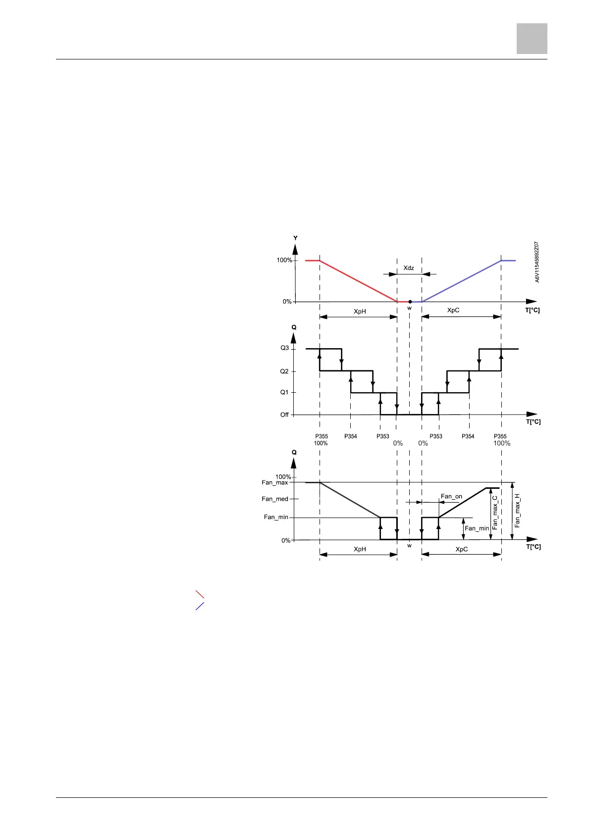
For 3-speed fan control:
The individual switching points for each fan stage can be adjusted via
P353…P355. The fan speed switch off point is 20% below the switch on point. The
diagrams below show fan speed control for modulating PI control.
For DC 0…10 V fan control:
If DC 0...10 V fan control is selected, the fan switching points are set using the
following parameters:
● P359 & P360: DC 0…10 V fan max. output
● P358: DC 0…10 V middle speed output
● P357: DC 0…10 V fan min. output
● P356: Switching point for fan
w Room temperature setpoint
Q Fan speed
YH Control demand "Heating"
YC Control demand "Cooling"
XpH Proportional band "Heating"
(P050)
XpC Proportional band "Cooling"
(P052)
X
dz
Dead zone (P055)
Fan speed switching point
high (P355)
Fan speed switching point
med (P354)
Fan speed switching point low
(P353)
Fan_max Max. DC 0...10 V fan speed
(P359 for heating & P360 for
cooling)
Fan_med Med. DC 0...10 V fan
speed
(P358)
Fan_min Min. DC 0...10 V fan speed
(P357)
Fan_on Fan switch-on point (P356)
The diagram only shows the proportional part of PI control.
Fan control with
modulating
heating/cooling control
(PWM, 3-pos or
DC 0...10 V)
 Loading...