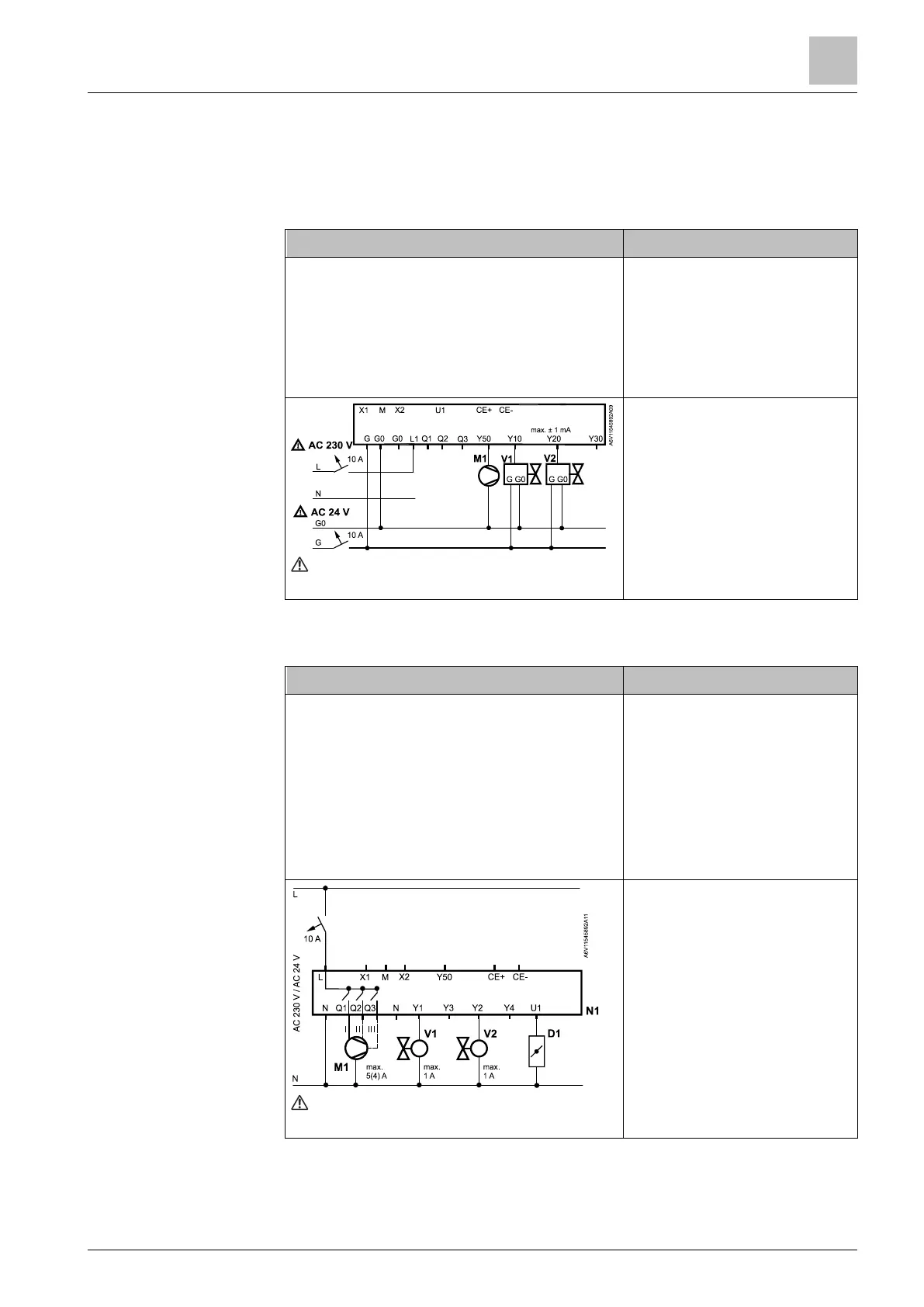
6.4.4 IAQ -CO2 control (RDG2..KN)
4-pipe heating and cooling fan coil system, for DC valves and fan, with IAQ
indication (text) on the display:
● Application 4-pipe
● Fan P351 = 3 (DC 0...10 V)
● Valve P201 = 5 (default)
● Valve P203 = 5 (default)
● Control strategy P450 = 0 (temp.)
● IAQ indication P009 = 7 (text)
● M1 DC 0...10 V fan
● V1 DC valve
● V2 DC valve
See Technical data [➙ 177] for min. and
max. ratings
4-pipe heating and cooling fan coil system, power supply 230 V, for PWM valves
and 3-speed fan, CO
2
indication (ppm) on the display, IAQ control via DC damper:
● Application 4-pipe
● Fan P351 = 2 (3-speed)
● Valve P201 = 3 (heating)
● Valve P203 = 3 (cooling)
● Control strategy P450 = 2 (default)
● Damper signal P453 = 1 (DC)
● IAQ setpoint P023 = 1000 (def.)
● IAQ indication P009 = 6 (ppm)
● M1 3-speed V fan
● V1 PWM valve H
● V2 PWM valve C
● D1 DC damper
See Technical data [➙ 177] for min. and
max. ratings
Example 1:
IAQ monitoring
Example 2:
IAQ control with DC
damper
 Loading...