19/44
Siemens RDG400 Basic Documentation CE1P3182en
Building Technologies 2015-05-20
4.7.3 Control outputs configuration
(setting via DIP 4/5 and parameters P46/P47)
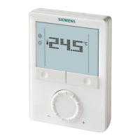
Control outputs
Application
ê
On/Off
(2-position)
Modulating
PWM
(2-position)
Modulating
3-position
Modulating
DC 0…10 V
Single-duct
ü ü
Single-duct and electric heater ü ü ü ü
Single-duct and radiator/floor heating
ü ü ü ü
Single-duct heating/cooling coil
ü ü ü ü
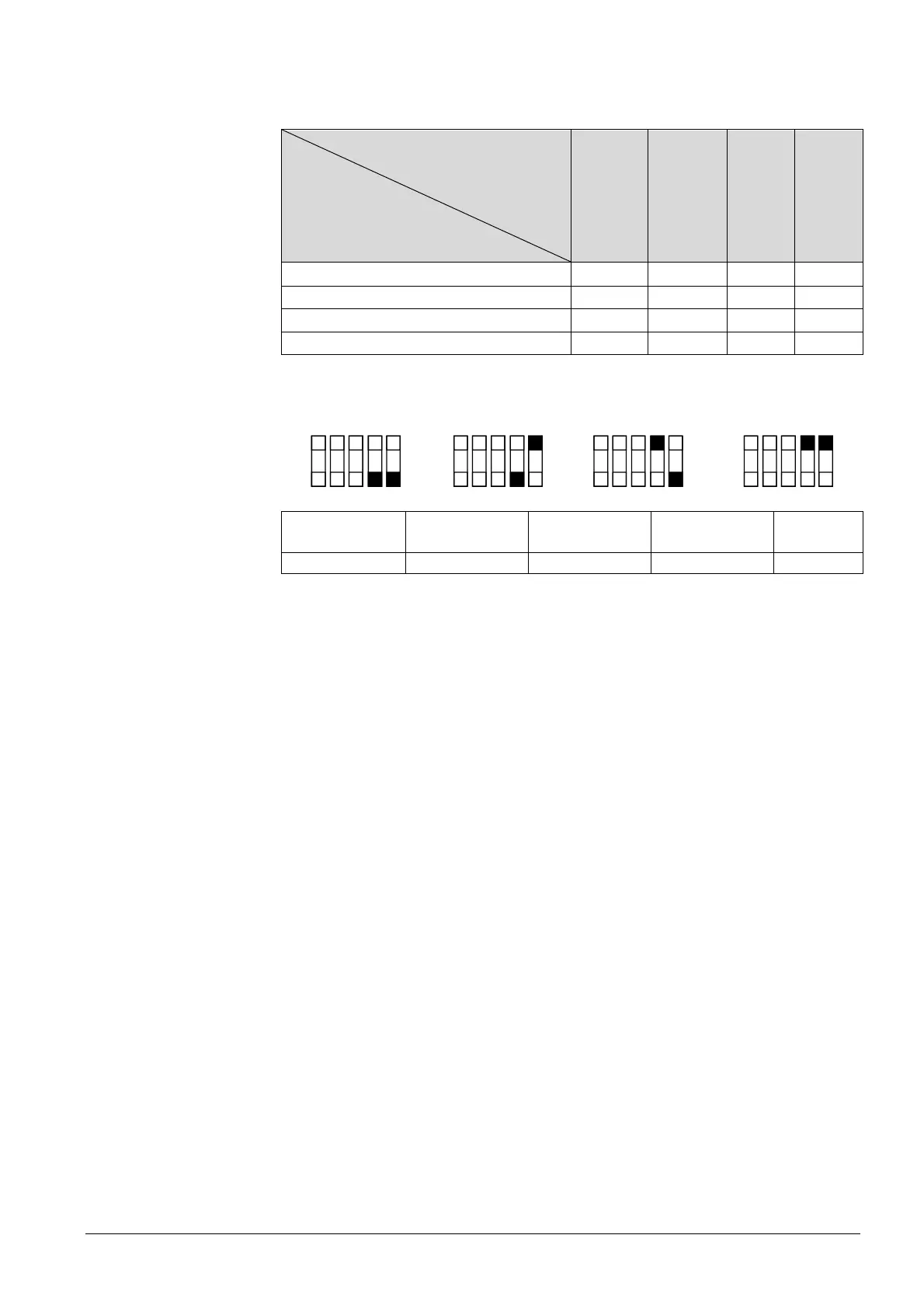
The function of the control outputs is set via DIP switches 4 and 5:
ON
OFF
12345
ON
OFF
12345
ON
OFF
12345
ON
OFF
12345
3181D101
DIP 4: Y10 = DC 0…10 V DC 0…10 V DC 10…0 V
(inverted)
DC 10…0 V
(inverted)
DIP 5: Y1/Y2 = 2-position 3-position 2-position 3-position
Y1, Y2:
If 2-position is selected, the factory setting is On/Off.
If you want PWM (pulse width modulation), set parameter P46 to 2 = PWM.
P47:
· 0 = VAV box DC 0…10 V control signal
· 1 = VAV box: 3-position control signal
For details concerning connection of peripheral devices and setting of the DIP
switches, refer to Mounting Instructions M3182 [3].
Note:
 Loading...