38/44
Siemens RDG400 Basic Documentation CE1P3182en
Building Technologies 2015-05-20
6.2 Connection diagrams
For details concerning connection of peripheral devices and setting of the DIP
switches, please refer to Mounting Instructions M3182 [3].
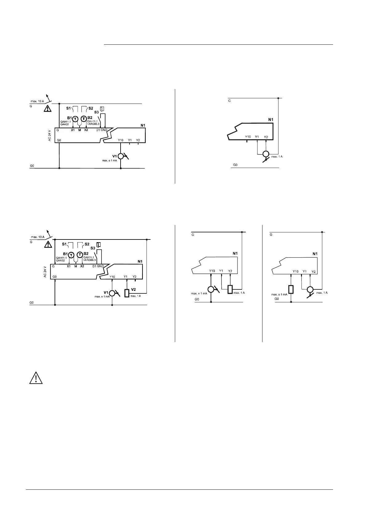
Application: Single-duct
V1 DC 0…10 V damper actuator V1 3-position damper actuator
N1 Room thermostat RDG400
S1..S3 Switch (keycard, window contact, etc.)
B1, B2 Temperature sensor (return air temperature, external room temperature, changeover sensor, etc.)
Application: Single-duct with electric heater, radiator or heating/cooling valve
V1
V2
V1 DC 0…10 V damper actuator
V2 On/Off or PWM electric heater, radiator or heating/cooling
valve
V1 DC 0…10 V damper actuator
V2 3-position electric heater,
radiator or heating/cooling
valve
V1 3-position damper
actuator
V2 DC 0…10 V electric
heater, radiator or
heating/cooling valve
N1 Room thermostat RDG400
S1..S3 Switch (keycard, window contact, etc.)
B1, B2 Temperature sensor (return air temperature, external room temperature, changeover sensor, etc.)
For US installations, use Class 2 rated power supplies.
For other installations, use circuit breakers with rated current of no more than 10 A.
Note:
 Loading...