23/44
Siemens RDG400 Basic Documentation CE1P3182en
Building Technologies 2015-05-20
4.7.7 Single-duct with heating/cooling coil
On single-duct applications with heating/cooling coil, the thermostat controls an
actuator (air damper, VAV system, etc.) plus a heating/cooling water coil.
The output signal for the air flow can be limited to a minimum and maximum value
if required (see section 4.6 for details).
The thermostat controls the reheating/cooling water valve either in heating/cooling
mode with changeover (automatic or manual), heating only, or cooling only. Cooling
only is factory-set (P01 = 01).
If the room temperature is above the setpoint for cooling, the valve will receive an
OPEN command and the air flow signal starts to rise to maintain the room
temperature setpoint.
If the room temperature drops below the setpoint for heating, then the valve will
receive an OPEN command.
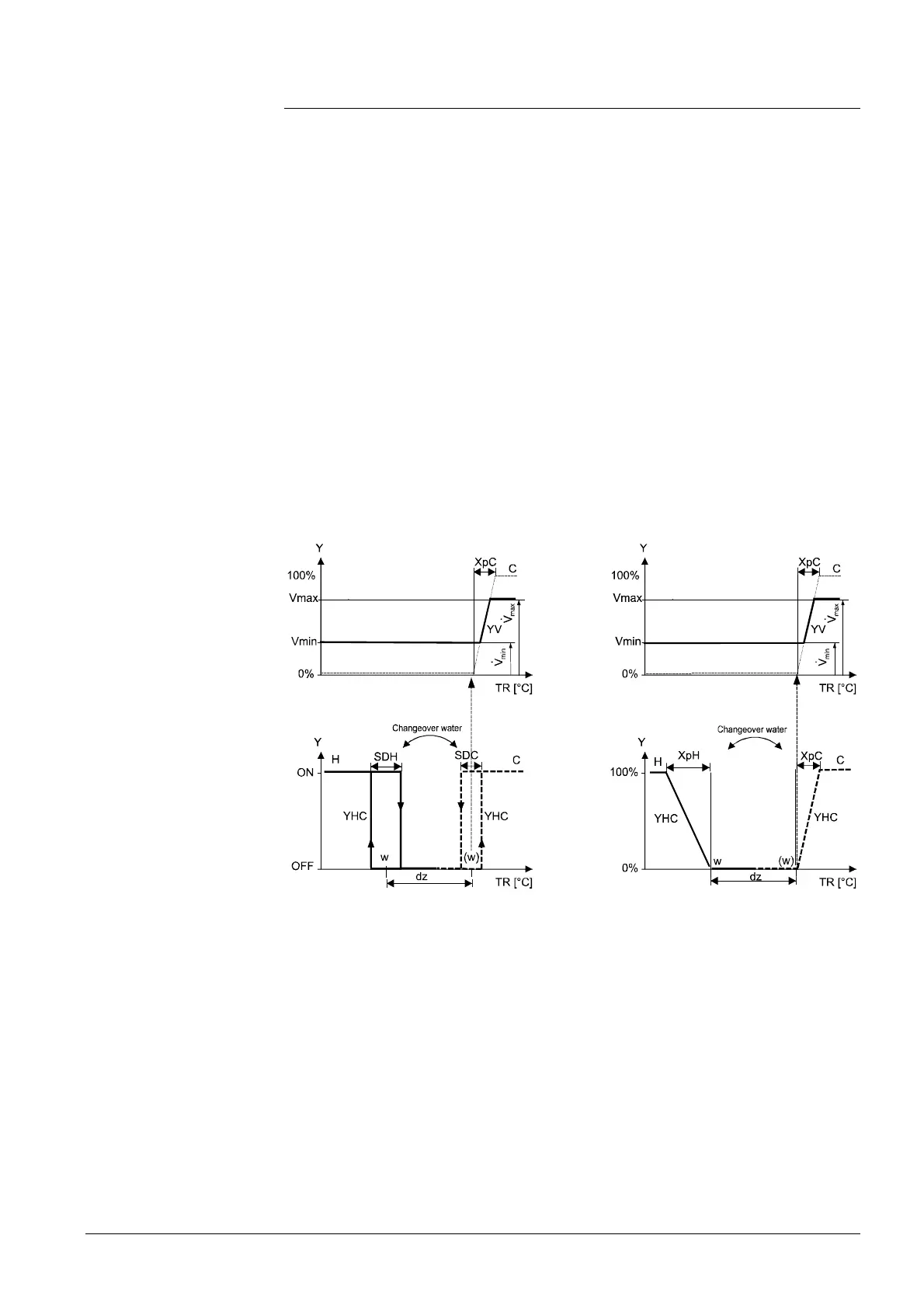
The diagrams below show the control sequence for modulating PI control in
Comfort mode.
On/Off heating/cooling coil Modulating heating/cooling coil
Y Output signal
TR Room temperature
w Comfort setpoint when heating sequence active
(w) Comfort setpoint when cooling sequence active
H Heating sequence
C Cooling sequence
YV Volume flow rate
XpH Proportional band heating
XpC Proportional band cooling
Vmin Minimum volume output
Vmax Maximum volume output
SDH Switching Differential Heating
SDC Switching Differential Cooling
The diagrams show the PI controller's proportional part only.
Setting the sequence and the control outputs
Refer to section 4.5, 4.7.1 and 4.7.3 for details.
Single duct with
heating/cooling coil
Water coil valve in
cooling mode
Water coil valve in
heating mode
Control sequence
Note:
 Loading...