24/44
Siemens RDG400 Basic Documentation CE1P3182en
Building Technologies 2015-05-20
4.8 Control outputs
Different control output signals are available depending on the configuration of
thermostat via DIP switches 4 and 5, and parameters P46 and P47.
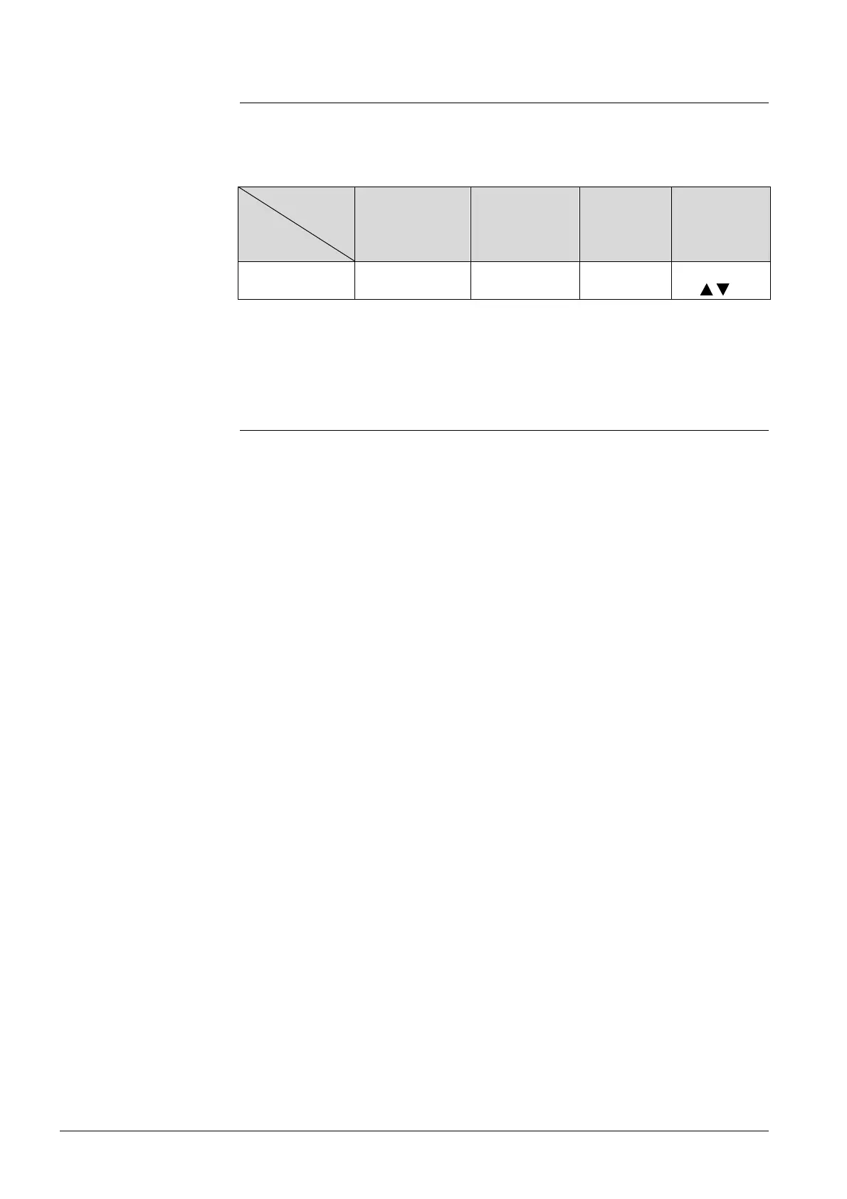
Control output
Product No.
Modulating
DC 0…10 V
2-position
On/Off
2-position
PWM
Modulating
3-position
RDG400 Y10 Y1 Y1 Y1/Y2
(1 x
/ )
Refer to section 4.7.3 for how to configure the control outputs.
4.8.1 Control output for air flow
The demand calculated by PI control from the current room temperature and
setpoint is provided to the valve actuator as a modulating DC 0...10 V signal via
output Y10.
A 3-position control output for an air damper has 2 control signals, one for the
"opening" command and one for the "closing" command. The thermostat has an
internal stroke model to calculate the position of the actuator. Therefore, the
running time from the fully closed to the fully open position must be adjusted via
parameter P44 (from 20…300 seconds; factory setting is 150 seconds).
On single-duct applications, a closing synchronization is effected to readjust the
internal stroke model to the real position of the actuator.
1. When the thermostat starts up, a closing signal (actuator running time + 150%
= 2.5 x running time) is delivered to ensure the actuator will be fully closed
and synchronized with the control algorithm.
2. Each time the thermostat calculates the fully closed position, the actuator’s
running time is extended + 150% to ensure the right position of the actuator.
3. When the actuator has reached the position calculated by the thermostat, a
waiting time of 30 seconds is observed to stabilize the outputs.
"Opening" synchronization is available for valve outputs only.
Overview of control
outputs
DC 0…10 V
control signal
3-position
control signal
Synchronization
Note:
 Loading...