Chapter 1
Introduction
RUGGEDCOM RMC30
Installation Guide
2 Description
• Support multiple Modbus masters
• Use Serial IP port redirection software to support PC applications statistics and built-in sniffer for
troubleshooting
Designed for Harsh Environments
• Operates over a temperature range of -40 to 85 °C (-40 to 185 °F) without the use of fans for improved
reliability
• 21 AWG galvanized steel enclosure suitable for DIN or panel mounting provide secure mechanical reliability
Section1.2
Description
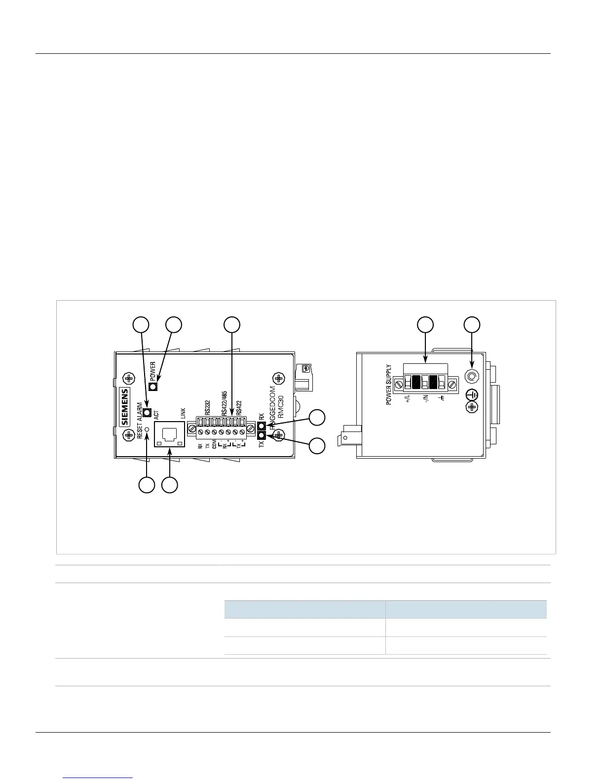
The RUGGEDCOM RMC30 features various ports, controls and indicator LEDs on the display panel for connecting,
configuring and troubleshooting the device. The display panel can be located on the rear, front or top of the
device, depending on the mounting configuration.
Figure1: RUGGEDCOM RMC30
1.ALARM LED 2.POWER LED 3.Serial Terminal 4.Reset Button 5.Copper Ethernet Port with LEDs 6.TX LED 7.RX LED
8.Power Terminal Block 9.Chassis Ground Terminal
ALARM LED Illuminates when an alarm condition exists.
POWER LED Illuminates when power is being supplied to the device.
State Description
Green Power is on
Off Power is off
RESET Button Shuts down and restarts the device. For more information, refer to Section2.4, “Resetting
the Device” .
TX/RX LEDs Indicate the connection status of the serial terminal.
 Loading...