Chapter 2
Installing the Device
RUGGEDCOM RMC30
Installation Guide
10 Connecting to the Device
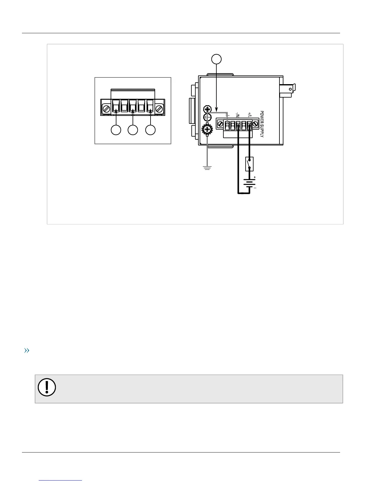
Figure5:Terminal Block Wiring
1.Positive/Live (+/L) Terminal 2.Negative/Neutral (-/N) Terminal 3.Surge Ground Terminal 4.Braided Ground Cable
2. Connect the negative wire from the power source to the negative/neutral (-/N) terminal on the terminal block.
3. Using a braided wire or other appropriate grounding wire, connect the surge ground terminal to the chassis
ground connection. The surge ground terminal is used as the ground conductor for all surge and transient
suppression circuitry internal to the unit.
4. Connect the ground terminal on the power source to the chassis ground terminal on the device.
Section2.3
Connecting to the Device
The following describes the various methods for accessing the RUGGEDCOM ROS console and Web interfaces on
the device. For more detailed instructions, refer to the RUGGEDCOM ROS User Guide for the RUGGEDCOM RMC30.
RS232/RS422/RS485 Serial Console Terminal
Connect a PC or terminal directly to the RS232 serial terminals to access the boot-time control and RUGGEDCOM
ROS console interface.
IMPORTANT!
The console interface is intended to be used only as a temporary connection during initial
configuration or troubleshooting.
The serial terminal implements RS232 DCE (Data Communication Equipment) on a Phoenix-style compression
connector. For more information, refer to Section3.2, “Serial Terminal” .
 Loading...