RUGGEDCOM RS900
Installation Guide
Chapter 2
Installing the Device
Connecting Low DC Power 15
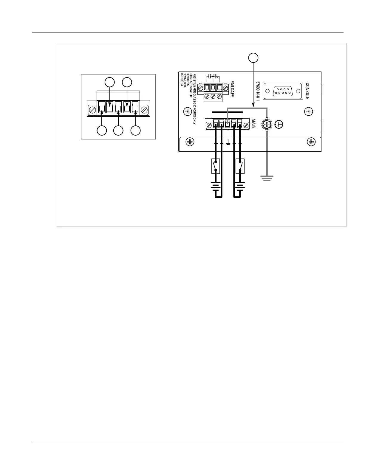
Figure9:Terminal Block Wiring – Dual DC Power Supply Inputs
1.Positive Terminal 2.Negative Terminal 3.Surge Ground Terminal 4.Braided Ground Cable
5. Using a braided wire or other appropriate grounding wire, connect the surge ground terminal to the chassis
ground connection. The surge ground terminal is used as the ground conductor for all surge and transient
suppression circuitry internal to the unit.
6. Connect the ground wire from the power source to the chassis groun terminal on the terminal block.
 Loading...