Introduction
1.3Required Tools and Materials
7
Power Supply Terminal Blocks
8
Chassis Ground Screw
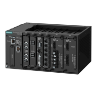
Figure1.1 RUGGEDCOM RSG910C
POWER LED Illuminates green when power is supplied to the device.
ALARM LED Illuminates red when an alarm condition exists.
Console Port The USB Type-B console port is for interfacing directly with the de-
vice and accessing initial management functions. For information
about connecting to the device via the serial console port, refer to
"Connecting to the Device (Page 19)".
Communication Ports Communication ports in general receive and transmit data, as well
as provide access to the RUGGEDCOM RUGGEDCOM RSG910C Web
interface. For more information about the various ports available,
refer to "Communication Ports (Page 21)".
Failsafe Alarm Relay Latches to default state when a power disruption or other alarm
condition occurs. For more information, refer to:
• "Connecting the Failsafe Alarm Relay (Page 11)"
• "Failsafe Alarm Relay Specifications (Page 26)"
Power Supply Terminal Blocks Pluggable terminal blocks for connecting one or more power
sources. For more information, refer to "Connecting Power (Page
13)" and "Power Supply Specifications (Page 25)".
Chassis Ground Terminal Protects the device from power surges and accumulated static elec-
tricity. For information about grounding the device, refer to "Con-
necting Power (Page 13)".
1.3 Required Tools and Materials
The following tools and materials are required to install the RUGGEDCOM RSG910C:
Tools/Materials Purpose
AC power cord (16 AWG) For connecting power to the device.
USB Type-B console port cable For connecting to the RUGGEDCOM RUGGEDCOM
RSG910C console interface.
CAT-5 Ethernet cables For connecting the device to a LAN.
Flathead screwdriver For mounting the device to a DIN rail.
Phillips screwdriver For mounting the device to a panel.
Torx screwdriver For attaching mounting brackets to the device.
4 x M5 or #10-24 screws For mounting the device to a panel.
1.4 Decommissioning and Disposal
Proper decommissioning and disposal of this device is important to prevent malicious
users from obtaining proprietary information and to protect the environment.
RUGGEDCOM RSG910C
Installation Manual, 02/2020, C79000-G8976-1405-06
3
 Loading...