Installing the Device
2.5.1Connecting AC or DC Power
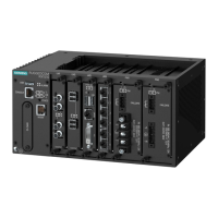
2. Insert the appropriate terminal block(s) into the device and tighten both screws.
Power Source Terminal Block Type
HI 3 POS
LO 5 POS
Figure2.8 Assembling the Power Ter-
minal Blocks
IMPORTANT
Torque all terminal connections to 0.6 N·m (5 lbf-in).
3. Connect the power cable to the device as follows:
HI Power Supply
a. Connect the Line wire (AC) or Pos-
itive wire (DC) to the positive/live
(+/L) terminal on the terminal
block.
b. Connect the Neutral wire (AC) or
Negative wire (DC) to the nega-
tive/neutral (-/N) terminal on the
terminal block.
c. Connect the ground wire to the
chassis/ground terminal on the
terminal block.
LO Power supply
a. Connect the Positive wire to the
positive (+) terminal on the termi-
nal block.
b. Connect the Negative wire to the
negative (-) terminal on the termi-
nal block.
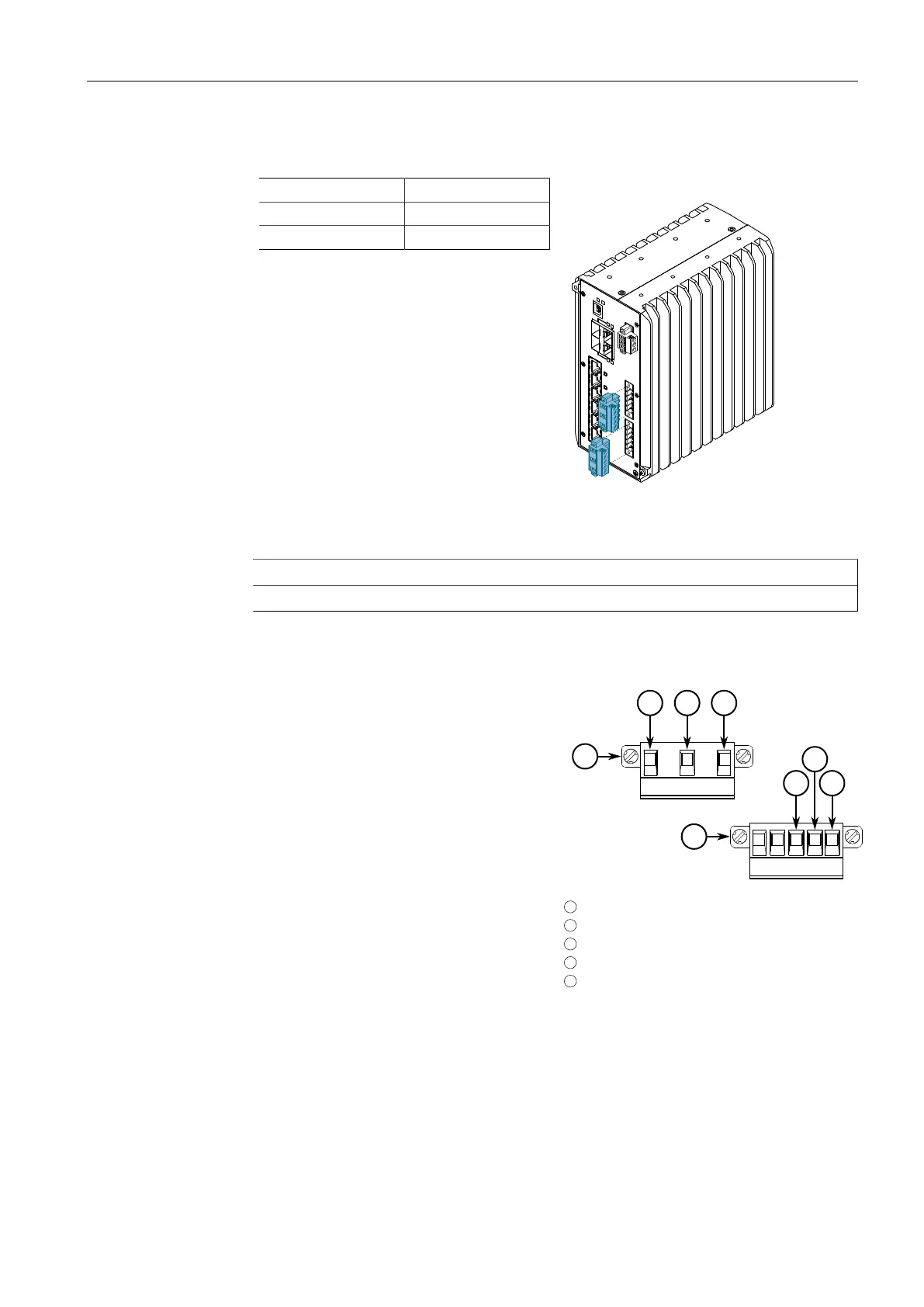
1
3 POS Terminal Block
2
5 POS Terminal Block
3
Chassis/Ground Terminal
4
Negative Terminal
5
Positive Terminal
Figure2.9 Terminal Block Wiring
14
RUGGEDCOM RSG910C
Installation Manual, 02/2020, C79000-G8976-1405-06
 Loading...