158/166
Siemens Building Technologies Basic Documentation RVA47.320 CE1P2379E
HVAC Products Application examples 15.07.2002
8.14 Legend
Low voltage side
Mains voltage side
DB Data bus (LPB) N Neutral conductor (mains connection)
MB Ground bus (LPB) L Live AC 230 V (mains connection)
A6 PPS (room unit, BMU...)
MD Ground PPS
B9 outside temperature sensor F1 Line control contact relay Q1/Q3
B10 Cascade flow temperature sensor Q1 Heating circuit pump / primary pump
B70 Cascade return temperature sensor
M Ground sensors Q3 D.h.w. charging pump
B3 D.h.w. temperature sensor / control
thermostat
H1 input H1
LPB Local Process Bus
(ALBATROS™-process bus)
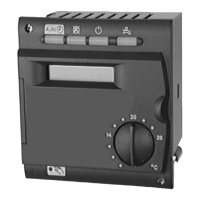
N1 ALBATROS™controller RVA47.320
PPS Point-to-point interface
(ALBATROS™ peripheral bus)
BMU Boiler Management Unit (burner control
with additional management functions)
The connection diagrams show optional components with broken lines.
For application examples with a cascade integrated in systems with alternative heat
generation, refer to Basic Documentation ”LPB System Engineering” (document no.
CE1P2379E).

 Loading...