20/93
Building Technologies Division User Manual RWF55... CC1U7867en
Infrastructure & Cities Sector 4 Electrical connections 05.11.2013
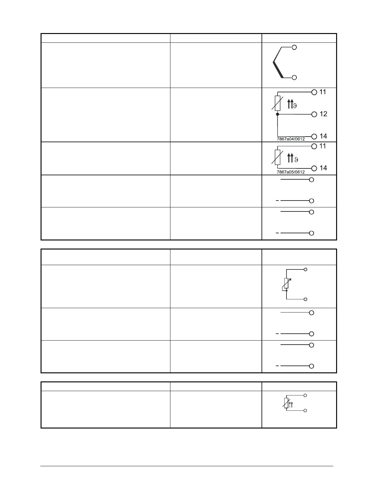
Analog input
InP1 (actual value) Terminal no.
Connection diagram
Thermal element 12
14
+12
-14
7867a13/0612
Resistance thermometer in 3-wire circuit
11
12
14
Resistance thermometer in 2-wire circuit
0...135 Ω
11
14
Current input
DC 0...20 mA, 4...20 mA
12 +
14 -
14
12
+
7867a06/0612
Ix
Voltage input
DC 0...5 V, DC 1...5 V, DC 0...10 V
13 +
14 -
14
13
+
7867a07/0612
Ux
Analog input
InP2 (external setpoint or setpoint
shifting)
Terminal no.
Connection diagram
Resistance thermometer in 2-wire circuit
0...1000
21
23
21
7867a14/0612
23
Current input
DC 0...20 mA, 4...20 mA
21 +
23 -
23
21
+
7867a23/0612
Ix
Voltage input
DC 0...5 V, 1...5 V, 0...10 V
22 +
23 -
23
22
+
7867a16/0612
Ux
Analog input
InP3 (outside temperature) Terminal no.
Connection diagram
Resistance thermometer in 2-wire circuit
31
32
31
7867a17/0612
32
 Loading...


