52/93
Building Technologies Division User Manual RWF55... CC1U7867en
Infrastructure & Cities Sector 8 Configuration ConF 05.11.2013
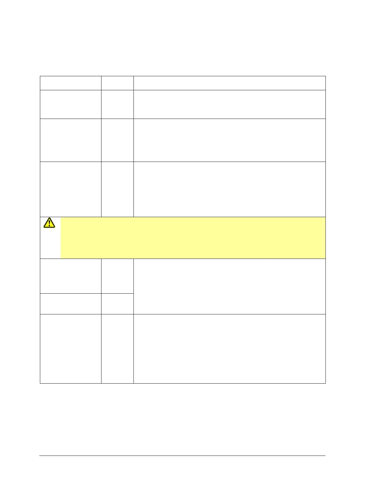
8.2 Analog input InP2
This input can be used to specify an external setpoint or carry out setpoint shifting.
ConF InP InP2
Parameter Value/
selection
Description
Function
FnC2
0 No function
1 External setpoint (display SPE)
2 Setpoint shifting (display dSP)
3 Angular positioning feedback
Sensor type
SEn2
Sensor type
1 0...20 mA
2 4...20 mA
3 0...10 V
4 0...5 V
5 1...5 V
6 Resistance teletransmitter
Correction of
measured value
OFF2
Offset
-1999...
0...
+9999
Using the measured value correction function (offset), a measured value can
be corrected by a certain amount, either up or down.
Example:
Measurement value Offset Display value
294.7 +0.3 295.0
295.3 -0.3 295.0
Caution!
Measured value correction:
To make the calculation, the controller uses the corrected value (displayed value). This value does not
represent the value acquired at the point of measurement.
If the measured value correction function is used incorrectly (e.g., overcompensation of measured values
measurement error only present temporarily), this may lead to undesirable plant states.
Start of display
SCL2
Scale low level
-1999...
0...
+9999
In the case of a measuring transducer with standard signal, the physical
signal is assigned a display value here.
Example: 0…20 mA = 0…1500 °C
The physical signal range can be undershot/exceeded by 20% without a
measuring range overshoot/undershoot signal being issued.
End of display
SCH2
Scale high level
-1999...
100...
+9999
Filter time constant
dF2
Digital filter
0.0...
2...
100.0...
Is used to adapt the digital 2nd order input filter (time in s; 0 s = filter off).
If the input signal changes abruptly, about 26% of the change is captured
after a time corresponding to the filter time constant dF (2 x dF: approx. 59%;
5 x dF: approx. 96%).
If the filter time constant is large:
- High attenuation of interference signals
- Slow response of actual value display to changes in the actual value
- Low limit frequency (low-pass filter)
 Loading...


