21/93
Building Technologies Division User Manual RWF55... CC1U7867en
Infrastructure & Cities Sector 4 Electrical connections 05.11.2013
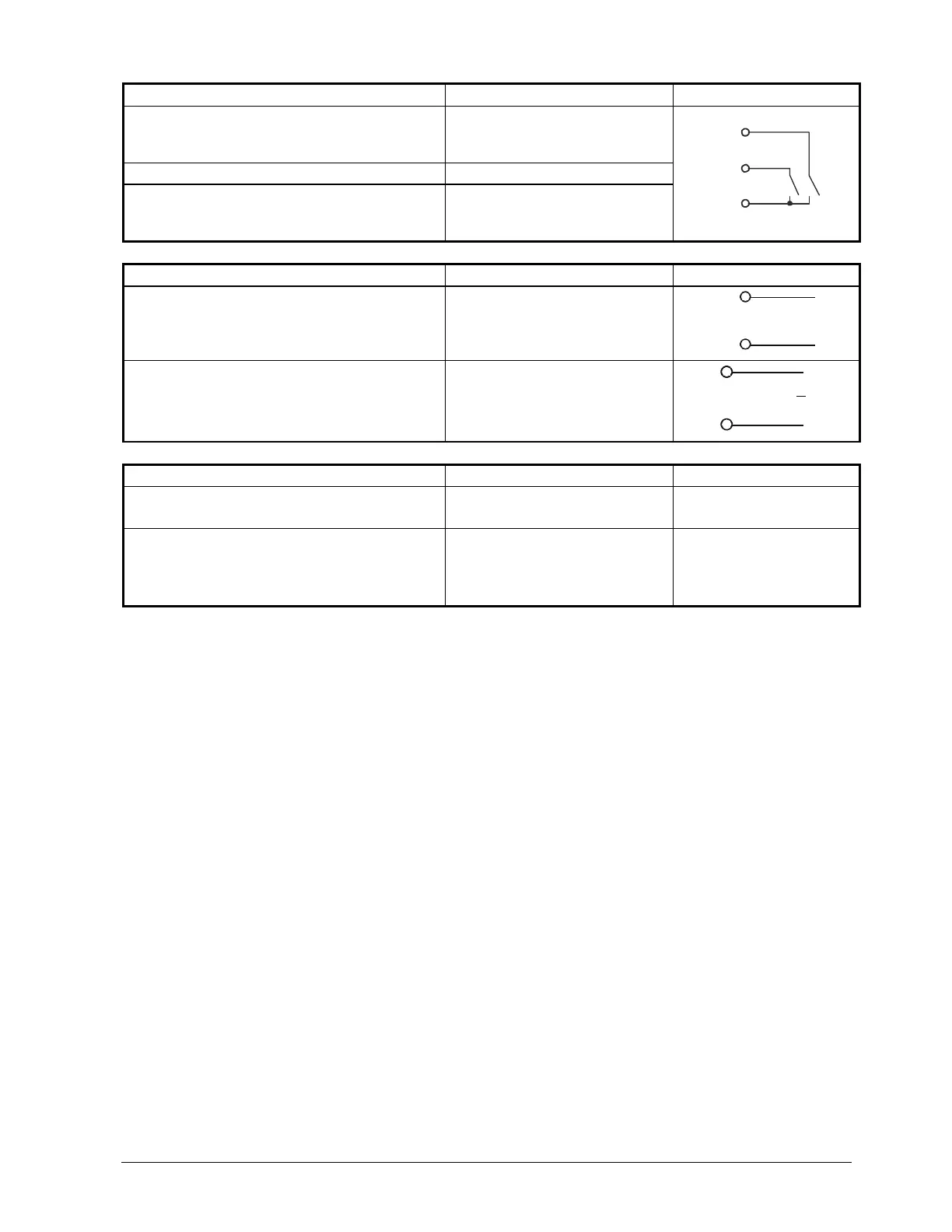
Binary inputs binF Terminal no.
Connection diagram
Binary input D1
D1
D1
7867a18/0612
D2
DG
Binary input D2 D2
Common ground DG
DG
Power supply Terminal no.
Connection diagram
Power supply
AC 110...240 V +10%/-15%, 48...63 Hz
L1 Live conductor
N Neutral conductor
L1
N
7866a09/0911
Power supply measuring transducer
(short-circuit-proof)
G+
G-
G+
G-
+
-
7867a10/0612
DC 24 V 10%
max. 30 mA
+
Interface Terminal no.
Connection diagram
RS-485 R+
R-
RxD/TxD +
RXD/TxD -
Only RWF55.6
Profibus DP
C1
C2
C3
C4
VP (+5 V)
RxD/TxD-P (B)
RxD/TxD-N (A)
DGND
 Loading...


