Communication with S7 CPU via KNX Gateway
Entry ID: 109739689, V1.0, 06/2017
Siemens AG 2017 All rights reserved
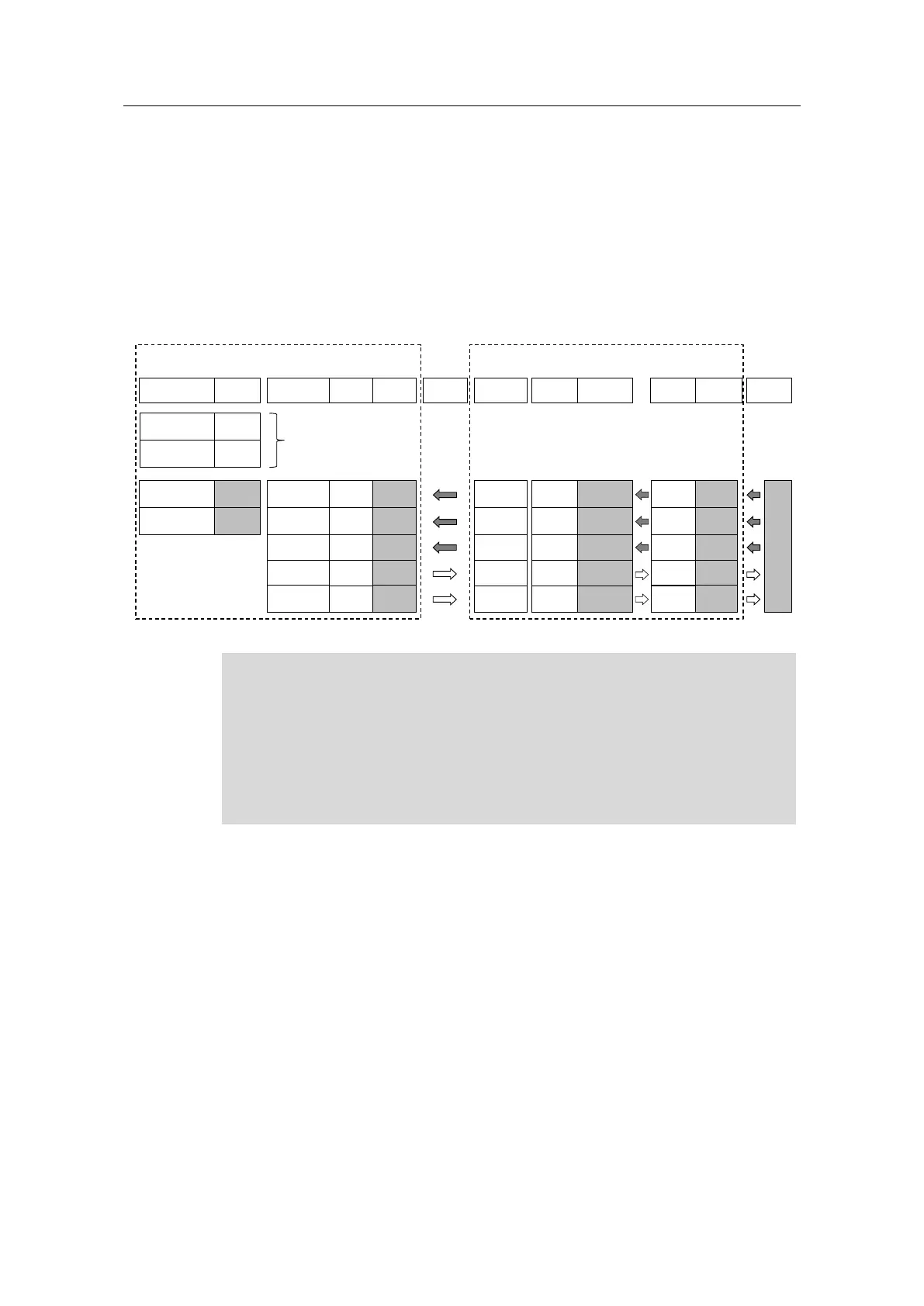
3.2 Data point mapping
The following figure shows all of the data used and the process image of the S7-
1200 CPU for the configuration with the gateway.
Please note: The input or output signal type always refers to the “perspective” of
the respective device.
Figure 3-2: Interaction between the process image of the S7 CPU and the data points in the gateway
OW 100
IW 100
O 102.0
O 102.0
setValInt
readValInt
setValBool
readValBool
PLC tags
Gateway
Name Data type
Length
Address Name AddressFormat
Length
PROFINET
S7-1200 CPU
Integrated
I/O
KNX-->S7
value
S inbyte 0SINT16
2 bytes
S7-->KNX
statusLED
M outbit 2.0BIT
1 bit
KNX-->S7
switch
S inbit 2.0BIT
1 bit
S7-->KNX
value
M outbyte 0
SINT16
2 bytes
INT
2 bytes
INT
2 bytes
BOOL
1 bit
BOOL
1 bit
PROFINET
AddressFormat
Length
M 1/1/1SINT16
2 bytes
S 1/1/4
UINT1
1 bit
M 1/1/3UINT1
1 bit
S 1/1/2SINT16
2 bytes
EIB/KNX
KNX
Process image
PLC_1 DI14
I 0 *
I/O Address
INPUT_32B_1 I
100..131
OUTPUT_32B_1 O
100..131
O 0 *
PLC_1 DO10_1
Data points
KNX devices
(wall switches, actuators…)
ID 103
readTemprInt REAL
4 bytes
KNX-->S7
temperature
Y inbyte 3
FLOAT32
4 bytes
X 1/1/5SFLOAT
2 bytes
*Compact CPUs (e.g., S7-1200) with integrated digital inputs and outputs:
In STEP 7 (TIA Portal), the smallest address 0 is automatically assigned to the
integrated digital inputs and outputs.
Other modules / I/O are automatically assigned to the next available address.
Here, the address space starting with 100 was selected in the process image.
This makes it easier to identify the connected tags between the S7-1200 CPU
and the gateway.

 Loading...


