4 Configuration and Project Engineering
Communication with S7 CPU via KNX Gateway
Entry ID: 109739689, V1.0, 06/2017
Siemens AG 2017 All rights reserved
4.4.6 “pnetd1.cfg” gateway file
The PROFINET device settings are made in the “pnetd1.cfg” configuration file.
When configuring, make sure that the STEP 7 configuration and the gateway’s
configuration file match exactly.
Table 4-8: Structure of the “pnetd1.cfg” gateway file
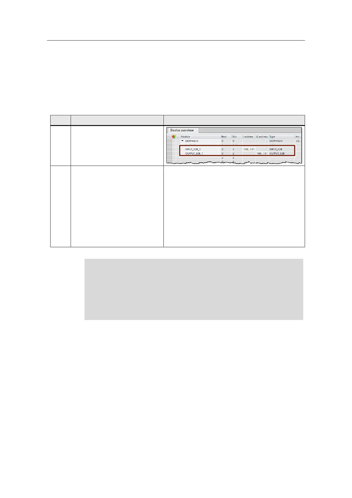
The device configuration of the
gateway can be found in STEP 7
(TIA Portal).
In the pnetd1.cfg configuration file,
the device configuration of the
gateway is programmed line by line
according to the device
configuration in STEP 7 (TIA Portal).
Each device is referred to as a
module (Mod001, Mod002,..).
For an example of how to
parameterize each module type,
please refer to the “pnetd1.cfg” file.
Mod001 = ID:0x16 IN:32 OUT:0 #INPUT_32B
Mod002 = ID:0x26 IN:0 OUT:32 #OUTPUT_32B
When configuring, please note the following:
All modules following “Mod001” must be numbered consecutively and
without gaps.
Upper limit: 60 modules (“Mod060”)
The configuration is not applied until a power cycle (turn off and back on) of
the gateway is complete.

 Loading...


