Description of the device
2.3 LED display
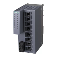
SCALANCE XP-200
30 Operating Instructions, 05/2016, C79000-G8976-C428-01
To set the required display mode, press the "SELECT/SET" button.
If you do not press the "SELECT/SET" button for longer than 1 minute, the device
automatically changes to display mode A.
Pressing SELECT/SET button
starting at display mode A
Press twice Off On Display mode C
The "L1" and "L2" LEDs indicate the current range of the power supply at connectors L1 and
L2.
The meaning of the "L1" and "L2" LEDs depends on the set display mode, see section
"LEDs "DM1" and "DM2" (Page 29)".
Meaning in display modes A, B, C and E
In display modes A, B, C and E, from the "L1" and "L2" LEDs you can see whether the
power supply is higher or lower than a certain voltage limit.
Table 2- 1 Power supply with devices with 24 VDC
Table 2- 2 Power supply with devices with 54 VDC

 Loading...