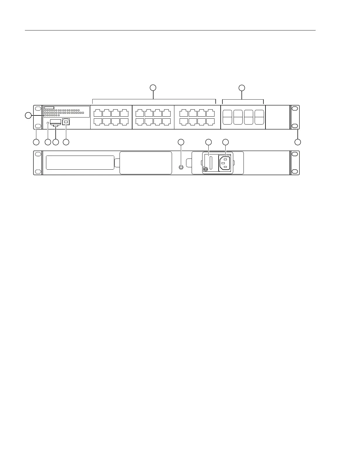
4.2.6 SCALANCE XR524-8WG 100 ... 240 V AC / 110 ... 250 V DC
The following gure shows an overview of the components of a 100 to 240VAC / 110 to
250VDC device version of the SCALANCEXR524-8WG.
① Electrical ports with 10/100/1000Mbps without securing collar
② Slots for SFP/SFP+ plug-in transceiver with 1/10 Gbps
③ Mounting brackets for 19" rack installation
④ Connection to the 100…240V AC power supply
⑤ Connection to the 110 to 250VDC power supply (hidden behind a screw-retained cover)
⑥ Grounding bolt for connection of protective grounding
⑦ USB console interface (2.0 port, Type B, serial via USB)
⑧ CLP slot with an inserted CLP
⑨ "SELECT/SET" button
⑩ LED display
• Port LEDs
• "F" LED for the fault display
• "L1/L2" LED for the power supply
• "RM" LED for the redundancy manager function
• "SB" LED for the status of the standby function
• "DM1/DM2" LED for the display mode
Figure4-6 SCALANCE XR524-8 100 ... 240 V AC / 110 ... 250 V DC, front and rear
Description of the device
4.2Device views
SCALANCE XR-500
32 Operating Instructions, 07/2023, C79000-G8976-C692-01
 Loading...