Information on the signaling contact
• The signaling contact is a oating switch that signals error states by interrupting the contact.
If an error occurs, the signaling contact opens. In normal operation, the signaling contact is
closed.
• The signaling contact is connected using a 2-pin plug-in terminal block (spring-loaded
terminal). The terminal block is included in the scope of delivery of the device and can be
ordered as a spare part, see section "Spare parts (Page36)".
• Note the wiring rules (Page65).
• The signaling contact can be controlled manually via the user interfaces. Information on this
can be found in the Conguration manuals.
WARNING
Risk of electric shock and property damage due to voltage being too high
The signaling contact can be operated in the voltage range of 19.2 to 31.2 V DC or 19.2 to 30.0
V AC and subjected to a maximum load of 100mA.
With higher voltages or currents, there is a risk of electric shock and damage to the device.
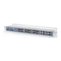
Position and assignment
The connection is located on the front of the device.
Figure6-7 Position of the signaling contact using a 24VAC/DC device version with 12 SFP/SFP+ slots
as an example
Contact Assignment
F1 Fault contact 1
F2 Fault contact 2
Signaling faults
• The signaling of errors by the signaling contact is synchronized with the fault LED "F", see
section ""F" LED (Page42)".
All errors that the fault LED "F" indicates (freely congurable) are also signaled by the
signaling contact.
• If an internal fault occurs, the fault LED "F" lights up and the signaling contact opens.
Connecting up
6.7Signaling contact
SCALANCE XR-500
82 Operating Instructions, 07/2023, C79000-G8976-C692-01
 Loading...