Description of the device
3.3 LED display
SCALANCE XR-500
30 Operating Instructions, 05/2017, A5E03275845-11
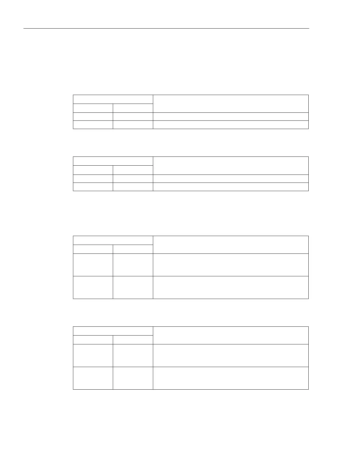
Meaning in display modes A, B, C and E
In display modes A, B, C and D, from the "L1" and "L2" LEDs you can see whether the
power supply is higher or lower than a certain voltage limit.
Table 3- 1 For devices with a 24 VDC power supply
Power supply lower than 17 VDC
Power supply higher than 17 VDC
Table 3- 2 Power supply for devices with 100 to 240 VAC
Power supply lower than 90 VAC
Green On Power supply higher than 90 VAC
Meaning in display mode D
In display mode D, the "L1" and "L2" LEDs indicate whether the power supply is monitored.
Table 3- 3 Monitoring for devices with 24 VDC
- Off Power supply is not monitored.
If the power supply falls below 17 VDC, the signaling contact does
not respond.
Green On Power supply is monitored.
If the power supply falls below 17 VDC, the signaling contact
Table 3- 4 Monitoring for devices with 100 to 240 VAC
- Off Power supply is not monitored.
If the power supply falls below 90 VAC, the signaling contact does
not respond.
Green On Power supply is monitored.
If the power supply falls below 90 VAC, the signaling contact re-

 Loading...