15 Project planning examples
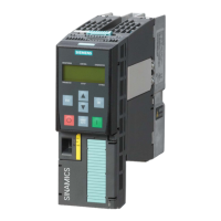
15.1 Layout of a SIGMALOOP at an existing star-configuration line network
Figure 26: SIGMALOOP at an existing star-configuration line network
If the above limits are observed, multiple incoming and outgoing loop lines can be fed via a
single cable, e.g. 1 loop for automatic detectors and 1 loop for non automatic detectors.
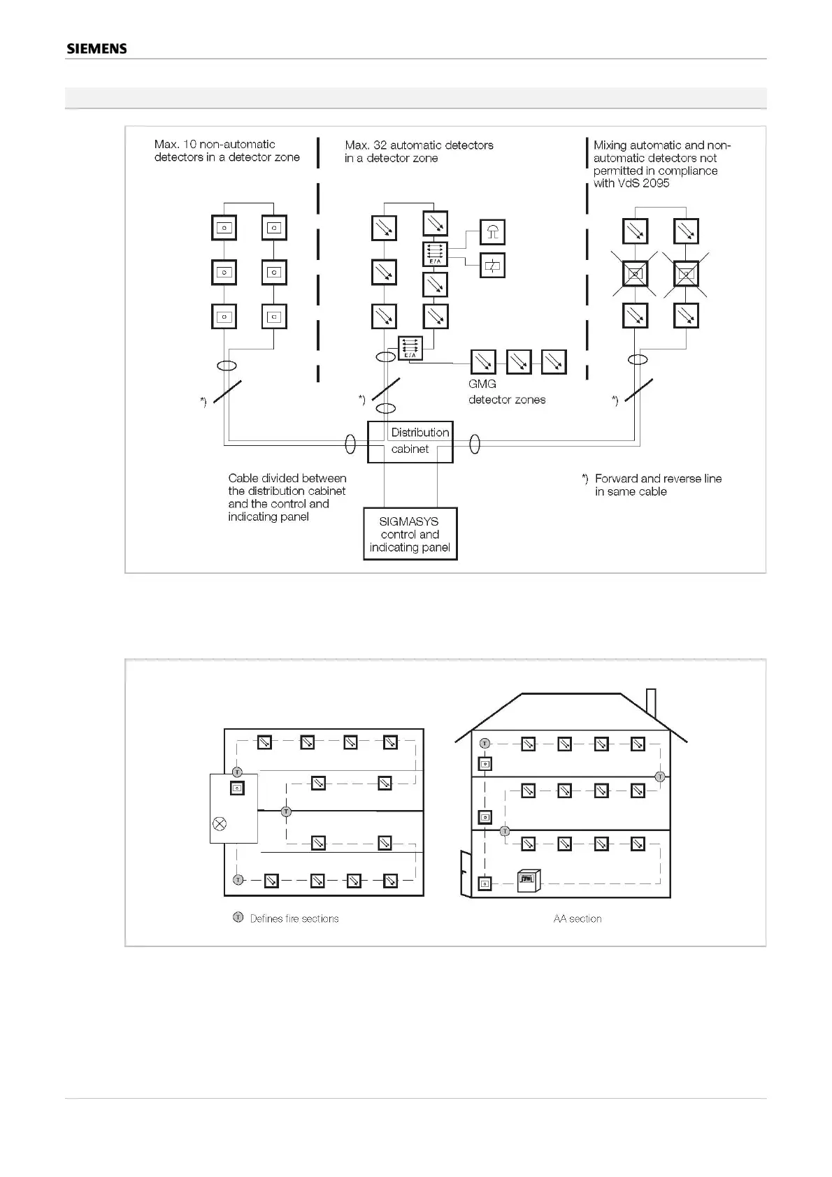
Figure 27: SIGMALOOP lines
If functional endurance is required of the cable (applicable building and construction law), this
can be achived by laying the loop in such a way that forward and reverse lines are fed via dif-
ferent fire sectors (riser ducts).
Multifunctional Danger Control and Indicating Panels SIGMASYS C and M (M-Modules) 111 / 128
Best.Nr. A24205-A337-B970 – Edition 12 (03/07)
 Loading...