Installing and connecting
2.3 Safety instructions for connection
Active field distributors AFD4, AFD4 (FM), AFD8 and AFS
Product Information, 02/2015, A5E03775304-AC
15
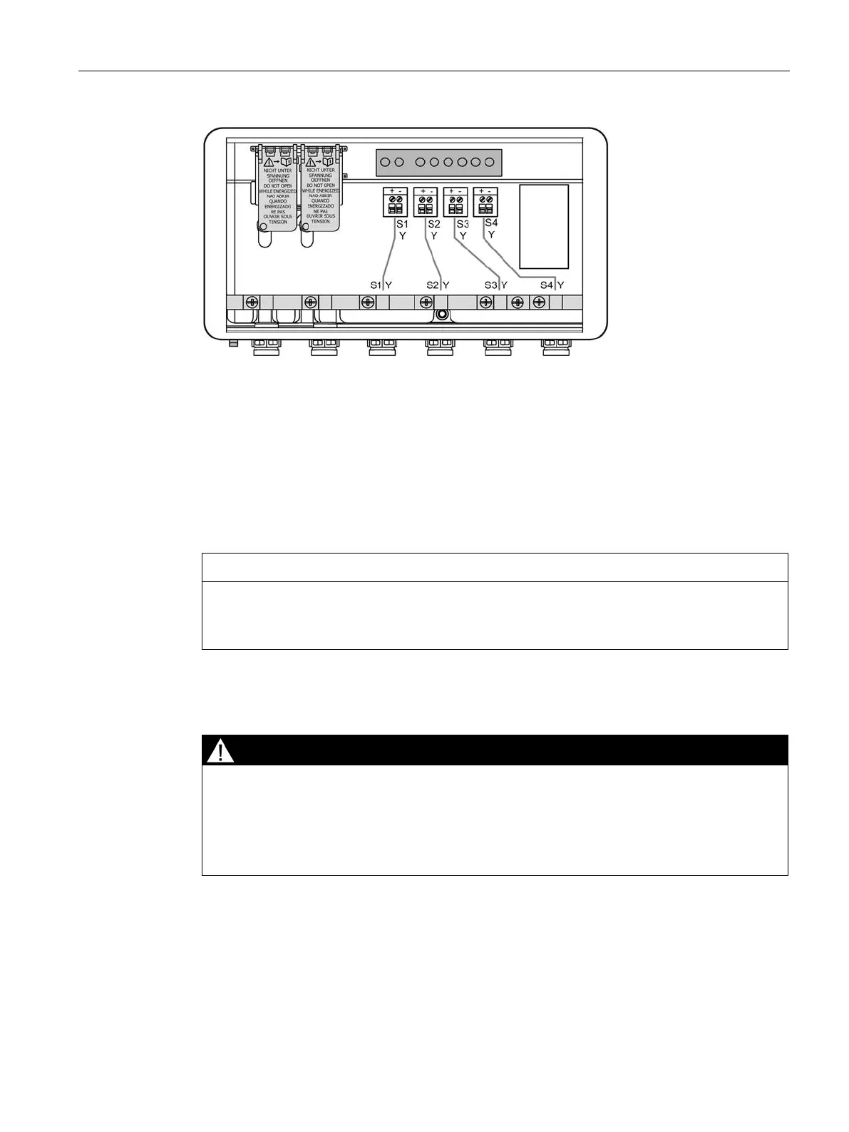
Figure 2-3 Schematic representation of the interior (AFD4 (FM))
IP30 cover for AFD4 / AFD4 (FM) / AFD8
The connections of the main cables inside the enclosure of the AFD4 / AFD4 (FM) / AFD8
are sealed with an IP30 cover. Opening the IP30 cover switches off the voltage supply to the
terminals and the feed lines.
In the hazardous area
, you are permitted to open the IP30 cover during operation for
visual inspection.
Despite the IP30 cover, the requirements for Zone 2 are not met because the AFS is
always connected directly to the FDC 157 coupler.
Zone 2: Disconnecting the main line / connecting the main line to AFD4 / AFD4 (FM) / AFD8
In hazardous area
, you are not permitted to disconnect the main line from an AFD4
/ AFD4 (FM) / AFD8 during operation if it is connected
to an FDC 157 coupler or an
AFS.
Before you start the work, disconnect the voltage supply to the FDC 157 coupler(s).
In hazardous area
, you are permitted to disconnect a main line from an AFD4 / AFD4
(FM) / AFD8 during operation if it connects two AFD4 / AFD4 (FM) / AFD8.