Wiring
3.1 Wiring and block diagram
Digital output module DQ 8x24VDC/0.5A SNK BA (6ES7132-6BF61-0AA0)
14 Manual, 09/2017, A5E32855878-AB
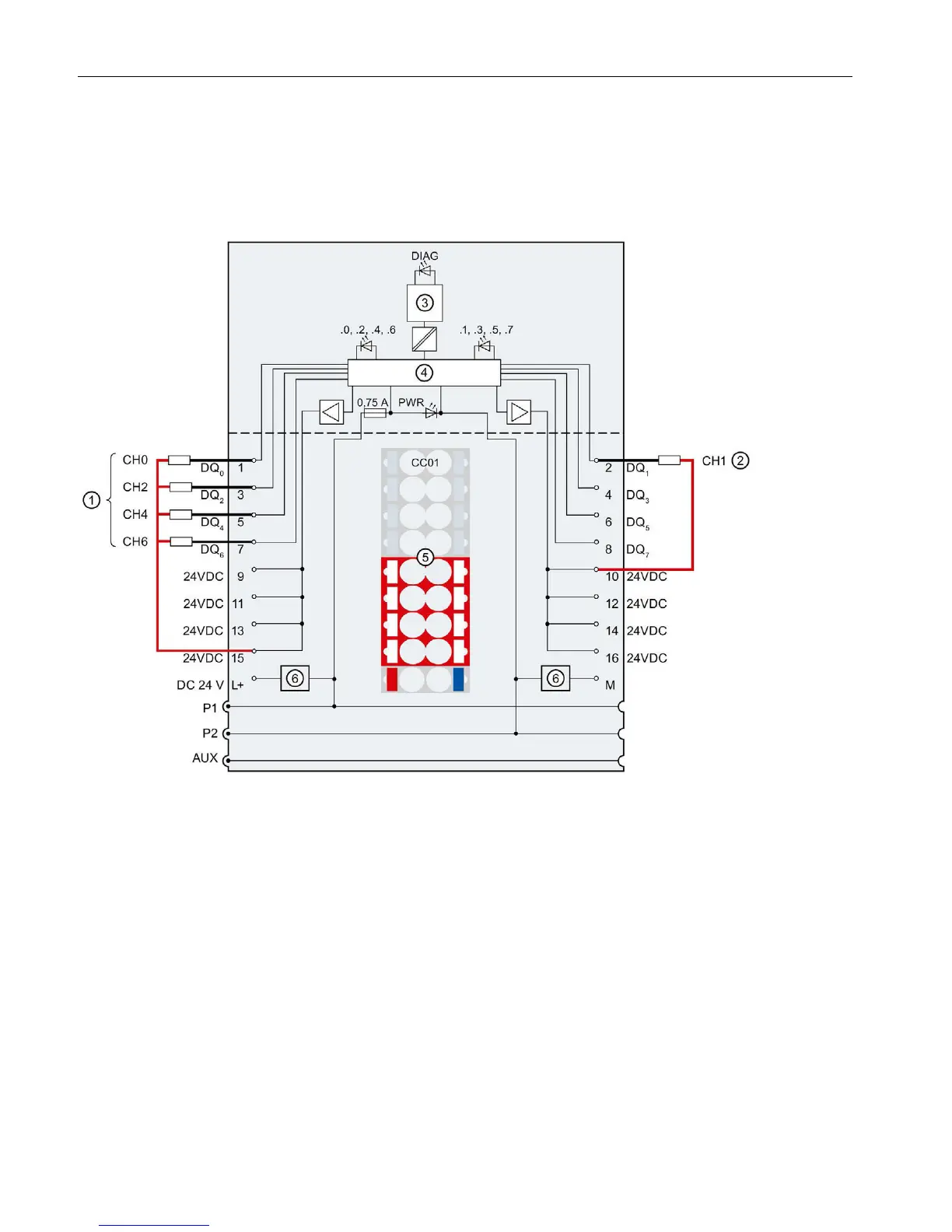
Connection: 1-wire and 2-wire connection
The following figure shows the block diagram and an example of the terminal assignment of
the digital input module DQ 8x24VDC/0.5A SNK BA on the BaseUnit BU type A0 without
AUX terminals (1-wire and 2-wire connection).
Encoder supply, channel n
24 V DC (feed for light-colored BaseUnit only)
Color identification label CCxx (optional)
Error or Diagnostics LED (green, red)
Filter connection supply voltage (only when
light-colored BaseUnit is present)
.0 to .7 Channel status LED (green)
P1, P2, AUX
Internal self-assembling voltage buses
Connection to left (dark-colored BaseUnit)
Connection to left interrupted (light-colored Ba-
PWR Power LED (green)
Figure 3-1 Wiring and block diagram for 1-wire and 2-wire connection of actuators.