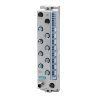
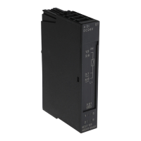
Digital output module DQ 8x24VDC/0.5A SNK BA (6ES7132-6BF61-0AA0)
Manual, 09/2017, A5E32855878-AB
15
Parameters
DQ 8x24VDC/0,5A SNK BA parameters
Specify the module properties with the various parameters in the course of your STEP 7
configuration. The following table lists the configurable parameters. The effective range of
the configurable parameters depends on the type of configuration.
The following configurations are possible:
● Central operation with an ET 200SP CPU
● Distributed operation on PROFINET IO in an ET 200SP system
● Distributed operation with PROFIBUS DP in an ET 200SP system
When assigning parameters in the user program, use the "WRREC" instruction to transfer
the parameters to the module by means of data records (see chapter Parameter assignment
and structure of the parameter data record (Page 25)).
Table 4- 1 Configurable parameters and their defaults (GSD file)
Scope with configuration software,
e.g. STEP 7 (TIA Portal)
• Disable
• Enable
Disable Yes Module Module
Channel
activated
• Disable
• Enable
Enable Yes Channel Channel
Reaction to
CPU STOP
• Turn off
• Keep last value
• Output substitute value 1
Turn off Yes Channel Module
Potential
group
• Use potential group of the
left module (module
plugged into a dark-colored
BaseUnit)
• Enable new potential group
(module plugged into light-
colored BaseUnit)
Use potential
group of the left
module
No Module Module
Only when configuring using a PROFIBUS GSD file; does not apply to configuration with STEP 7 via HSP. The parame-
ter assignment options are limited because PROFIBUS GSD configuration limits the number of parameters to a maxi-
mum of 244 bytes for each ET 200SP station. If required, you can still assign these parameters using the data record
128 as described in the column "GSD file PROFINET IO" (see table above). The parameter length of the I/O module is
 Loading...


