Wiring
3.2 Pin assignment
IM 157-1 DP (6ES7157-1AA00-0AB0)
Equipment Manual, 08/2021, A5E32100641-AE
15
3.2 Pin assignment
-Connection and the power supply of the modules are color-coded. These
colors correspond to the colors of the offered cables.
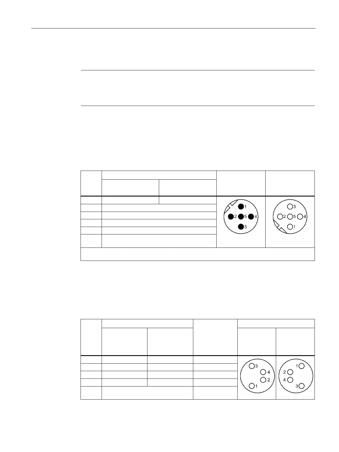
Pin assignment of the sockets for PROFIBUS
The following table shows the pin assignment of the connectors and sockets for the
connection of PROFIBUS.
Table 3- 1 Pin assignment for PROFIBUS
Pin
Front view of the
connector
X1 DP1
Front view of the
socket
X1 DP2
X1 DP1 connector
X1 DP2 Socket
Data reference potential M5*
* The voltage may only be used for supplying the external terminating resistor. It is not permitted to
loop-through the voltage by means of a cable to the next connector.
Pin assignment of the sockets for ET-Connection
The table below shows the pin assignments of the 2 sockets for the connection of
ET-Connection.
Table 3- 2 Pin assignment for ET-Connection
Pin
Assignment of
the wire color of
the bus line
cable for
Front view of the sockets
X30 socket
(ET-Connection1)
X31 socket
(ET-Connection2)
X30 X31
Shield-
Functional earth FE -

 Loading...


