EasyManuals Logo

Siemens simatic et200sp Equipment Manual

Siemens simatic et200sp
43 pages
To Next Page IconTo Next Page
To Previous Page IconTo Previous Page
Page #25 background imageLoading...
Page #25 background image
Wiring
CPU 1510SP-1 PN (6ES7510-1DJ01-0AB0)
24 Equipment Manual, 05/2021, A5E03506268-AD
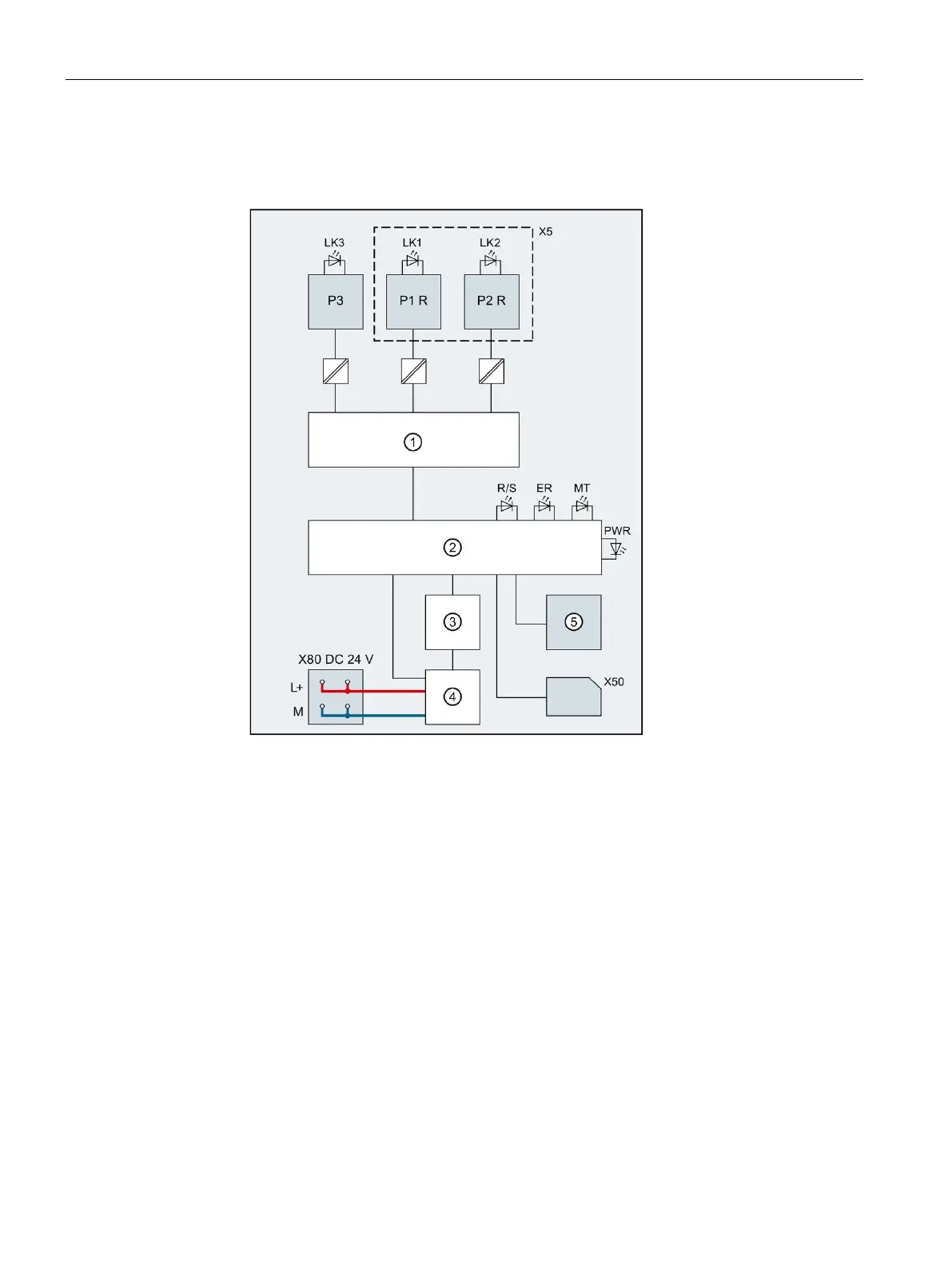
Block diagram
The following figure shows the block diagram of the CPU 1510SP-1 PN.
PROFINET switch
P1 R
PROFINET interface X1 Port 1
Electronics
P2 R
PROFINET interface X1 Port 2
Backplane bus interface
P3
PROFINET interface X1 Port 3
Internal supply voltage
L+
24 V DC supply voltage
RUN/STOP/MRES mode selector
M
Ground
X5
BusAdapter
LK1, 2, 3
LED Link TX/RX
X50
SIMATIC memory card
R/S
RUN/STOP LED (yellow/green)
X80 24 V DC
Infeed of supply voltage
ER
ERROR LED (red)
MT
MAINT LED (yellow)
PWR
POWER LED (green)
Figure 3-1 Block diagram of the CPU 1510SP-1 PN

Other manuals for Siemens simatic et200sp

Questions and Answers:

Question and Answer IconNeed help?

Do you have a question about the Siemens simatic et200sp and is the answer not in the manual?

Siemens simatic et200sp Specifications

General IconGeneral
CategoryI/O Systems
Power Supply24 V DC
Protection RatingIP20
Number of ModulesUp to 64 modules
MountingDIN Rail
Communication ProtocolsPROFINET, PROFIBUS
Storage Temperature-40 °C to +70 °C
Digital InputsYes (depending on module)
Digital OutputsYes (depending on module)
Analog InputsYes (depending on module)
Analog OutputsYes (depending on module)
ModularityModular
Relative Humidity5 to 95% (non-condensing)
WeightVaries by configuration
System TypeDistributed I/O

Related product manuals