EasyManuals Logo

Siemens simatic et200sp Equipment Manual

Siemens simatic et200sp
43 pages
To Next Page IconTo Next Page
To Previous Page IconTo Previous Page
Page #26 background imageLoading...
Page #26 background image
CPU 1510SP-1 PN (6ES7510-1DJ01-0AB0)
Equipment Manual, 05/2021, A5E03506268-AD
25
Interrupts, error messages, diagnostics and
system alarms
4
The status and error displays of the CPU 1510SP-1 PN are described below.
You will find additional information on "Interrupts" in the STEP 7 online help.
You can find additional information on the topics of "Diagnostics" and "System alarms" in the
Diagnostics (http://support.automation.siemens.com/WW/view/en/59192926) function
manual.
4.1 Status and error display of the CPU
LED displays
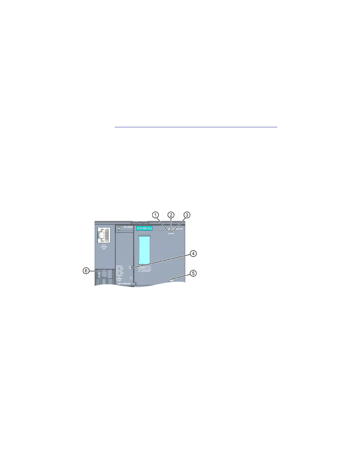
The figure below shows the LED displays of the CPU 1510SP-1 PN and the BA 2xRJ45
BusAdapter.
RUN/STOP LED (yellow/green LED)
ERROR LED (red LED)
MAINT LED (yellow LED)
LINK RX/TX LED for ports X1 P1 and X1 P2 (green LEDs on BusAdapter)
POWER LED (green LED)
LINK RX/TX LED for port X1 P3 (green LED on CPU)
Figure 4-1 LED displays on the CPU and BusAdapter

Other manuals for Siemens simatic et200sp

Questions and Answers:

Question and Answer IconNeed help?

Do you have a question about the Siemens simatic et200sp and is the answer not in the manual?

Siemens simatic et200sp Specifications

General IconGeneral
CategoryI/O Systems
Power Supply24 V DC
Protection RatingIP20
Number of ModulesUp to 64 modules
MountingDIN Rail
Communication ProtocolsPROFINET, PROFIBUS
Storage Temperature-40 °C to +70 °C
Digital InputsYes (depending on module)
Digital OutputsYes (depending on module)
Analog InputsYes (depending on module)
Analog OutputsYes (depending on module)
ModularityModular
Relative Humidity5 to 95% (non-condensing)
WeightVaries by configuration
System TypeDistributed I/O

Related product manuals