Installation
8-5
TP 070 Equipment Manual
Release 03/00
Configuration options
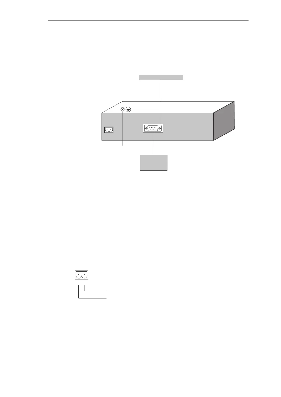
Figure 8-1 illustrates a number of configuration options for the operating unit, PLC
and configuration computer.
IF1B
Operating unit
Power supply
PLC
SIMATIC S7–200
Grounding connection
PC
PU 7xx
Configuration computer
RS485
Figure 8-1 Configuration options
Detailed information on connection options is provided in the following pages.
Information on the connection plug pin assignment for the interfaces are provided
in appendix B of this manual.
Power supply
The power supply for the operating unit is connected at the 2-pin plug connector on
the underside of the unit. Use the 2-pin terminal block supplied for this purpose.
The terminal block is designed for cables with a cross-section not larger than
2.5 mm
2
.
The figure illustrates a view of the underside of the unit.
GND
+24 V DC
12
Please refer to the technical data in appendix A for information on the power
supply requirements.