Overview
1.2 Structure of the devices
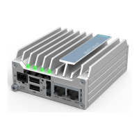
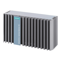
SIMATIC IPC227G
12 Operating Instructions, 07/2022, A5E50059933-AC
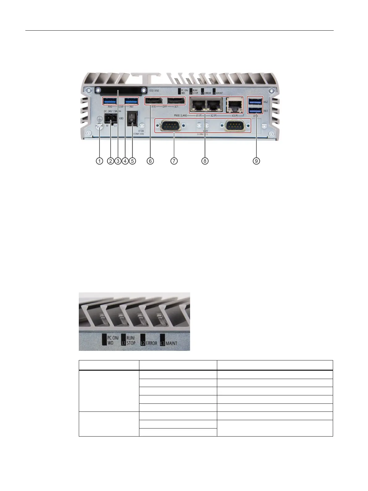
1.2.2 Interfaces of the device
Connection for Protective conductor
Connection for a 24 V DC power supply
Slot for M.2 NVMe/SATA SSD module
2 × USB 3.1 port, high current
Switch on (position "I"); Switch off (position "O")
2 × DisplayPort connection
2 × Serial interface, 9-pin RS232/RS422/RS485 D-sub connector
3 × RJ45 Ethernet connections for 10/100/1000 Mbps
2 × USB 3.1 port, high current
1.2.3 Status displays
Flashing green/yellow (1 Hz)
BIOS in POST, power switch on
Watchdog status display: active
RUN/STOP / L1
Can be controlled by user program/control
program (e.g. software controller)