WARNING
Operation above the voltage setting range
Under the given application conditions, ensure that the motor is not operated above the
voltage setting range by selecting the appropriate motor and gear unit; otherwise, the DC-link
voltage can increase above 60V DC with inactive control.
Reference
Note the detailed information on the power supply in the System Manual SIMATIC MICRO-DRIVE
Drive controller PDC (https://support.industry.siemens.com/cs/ww/en/view/109797859).
See also
Terminal assignment (Page19)
2.4 Calculating the overload capability of the power unit
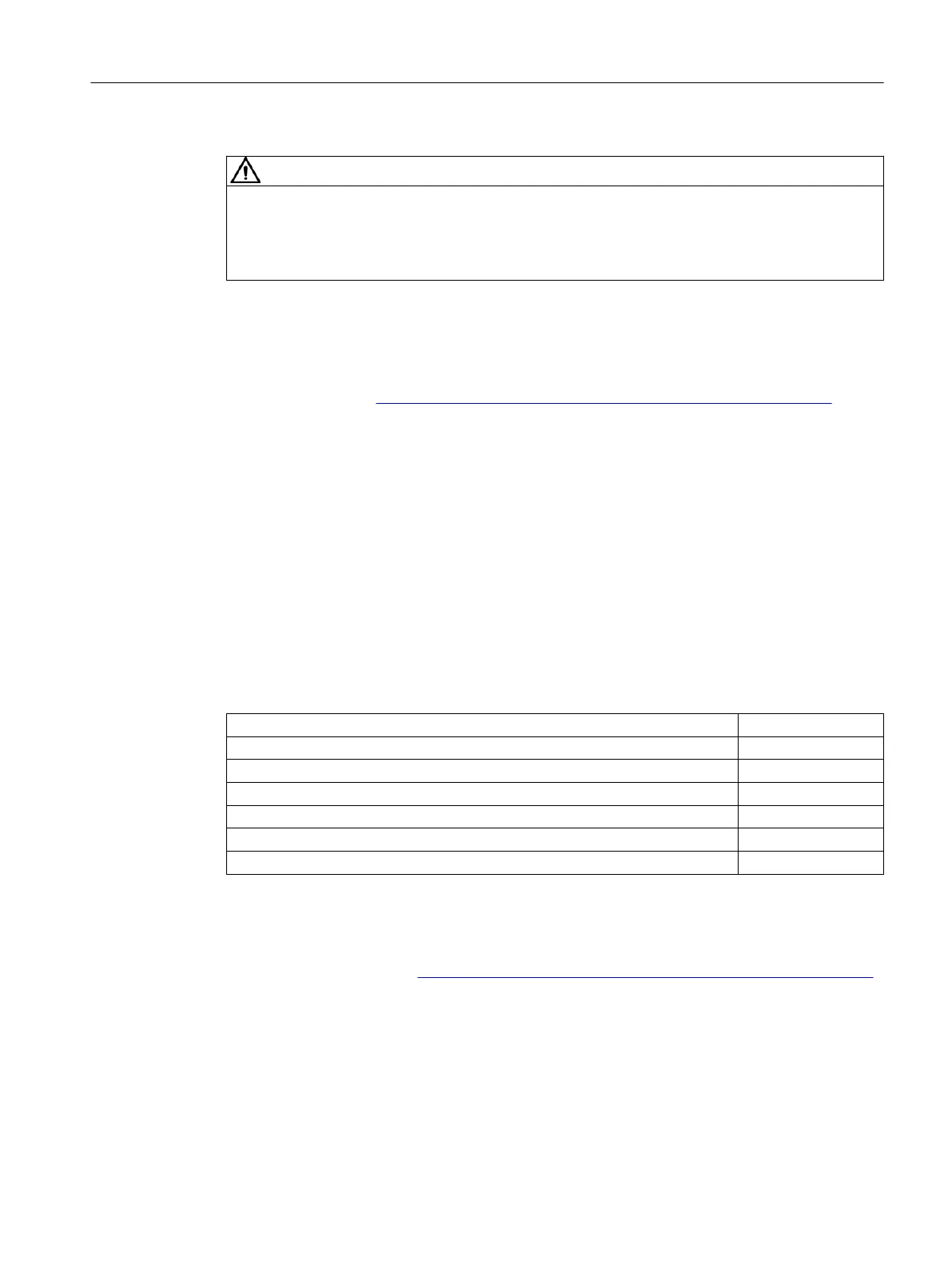
The following table shows the relationship between overload and recovery of the power unit.
Calculation
Table 2-2 Relationship between overload and recovery of the power unit
PDC600
Rated power unit current (r0208) 15.5A or 11A
e
Peak power unit current (r0209) 31A or 22A
e
Duration of overload (with peak current r0209) 3s
Duration of recovery (with I
recovery
) 17s
Reduced current I
recovery
(recovery of power unit) 10.7A or 7.6A
e
I
recovery
referenced to rated current (r0208) 69%
Reference
Note the detailed information on overload protection in the System Manual SIMATIC MICRO-
DRIVE Drive controller PDC (https://support.industry.siemens.com/cs/ww/en/view/109774126).
Product overview
2.4Calculating the overload capability of the power unit
PDC600(F)
Equipment Manual, 12/2023, A5E50502703-AB 17