3.2 Schematic circuit diagram
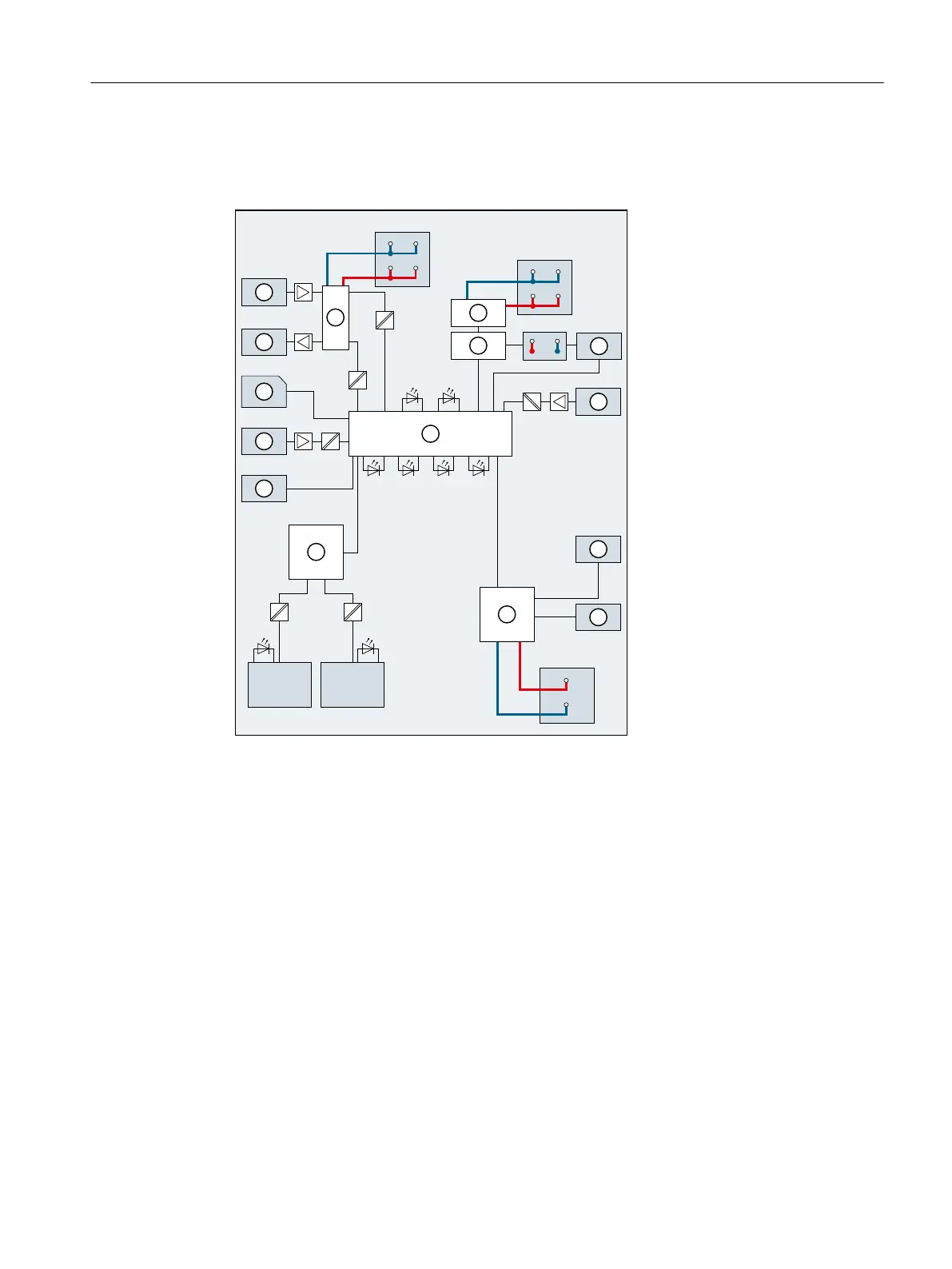
The following gure shows the schematic circuit diagram of the PDC600 drive controller.
/
;
'&9
;'&9
0
0
9696
3:5&+3105(6
6$)(
5'<
(55
31
3;
33
31
3;
;'&9
/
0
/
① X4060:
Connection for digital outputs
X4060
24VDC
Infeed of supply voltage for digital inputs/outputs
② X4060:
Connection for digital inputs
X5060
24VDC
Infeed of supply voltage for logic unit
③ Supply for digital inputs/outputs X5050
24-
48VDC
Infeed of supply voltage for power unit
④ Supply for logic unit PNP1
X2050
PROFINET interface Port1
⑤ EMC lter, current limitation PNP2
X2060
PROFINET interface Port2
⑥ X5060: SSI encoder connection xL+ Supply voltage
⑦ X5060: Hardware STO input xM Ground
⑧ Microcontroller unit, consisting of
drive controller, diagnostics controller
and communication controller
RDY/
ERR
PDC status LED (green/red)
⑨ X5055:
Motor phases
SAFE Safety function status LED (yellow)
Connecting
3.2Schematic circuit diagram
PDC600(F)
Equipment Manual, 12/2023, A5E50502703-AB 23