3.5 Connecting an external braking resistor
Connecting an external braking resistor
WARNING
Damage to braking resistor - Risk of re!
You must implement re prevention measures for the external braking resistor (e.g. re
protection housing, temperature fuse). The resistance of the externally connectable braking
resistor must be at least 3ohms.
Note
The connection terminal (X5051) for an external braking resistor is monitored by the drive
controller. In the event of a corresponding overload, warning A61059.22 (warning threshold I2t
monitoring connection of external braking resistor reached) is reported. If the limit value is
exceeded, the system is switched o with the alarm message F61059.18 (limit I2t monitoring
connection of external braking resistor exceeded).
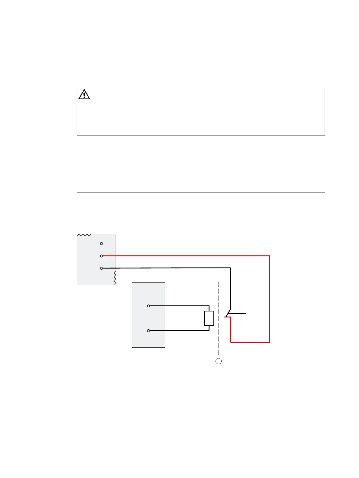
The gure below shows the connection of an external braking resistor to interface X5051
(and X4060):
/
',
5
5
5
;
;
˽
1
① Basic insulation 4R+, 4R- Connection for external braking resistor
xL+ Supply voltage R External braking resistor
2DIx Digital input
Figure3-5 Connection of external braking resistor (example)
Connecting
3.5Connecting an external braking resistor
PDC600(F)
28 Equipment Manual, 12/2023, A5E50502703-AB