Connections for motor phases
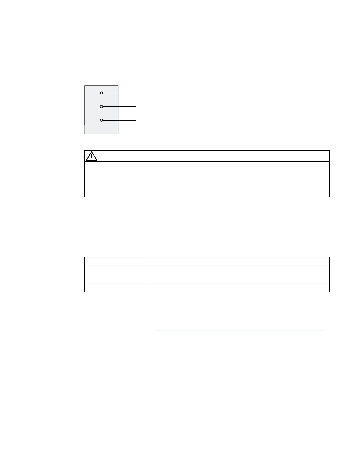
The gure below shows the connection of the motor phases to the interface X5055:
Figure3-4 Connection of motor phases of EC motors
WARNING
Operation above the voltage setting range
Under the given application conditions, ensure that the motor is not operated above the
voltage setting range by selecting the appropriate motor and gear unit; otherwise, the DC-link
voltage can increase above 60V DC with inactive control.
Pin assignment
• Interface X5055 for motor phases
Table 3-5 Pin assignment: Interface X5055 for motor phases
Designation Function
4U Motor phase U
4 V Motor phase V
4W Motor phase W
Reference
Note the detailed information on the topic "Connecting" in the System Manual SIMATIC MICRO-
DRIVE Drive controller PDC (
https://support.industry.siemens.com/cs/ww/en/view/109774126).
Connecting
3.4Connecting the motor
PDC600(F)
Equipment Manual, 12/2023, A5E50502703-AB 27