Plug connec‐
tor
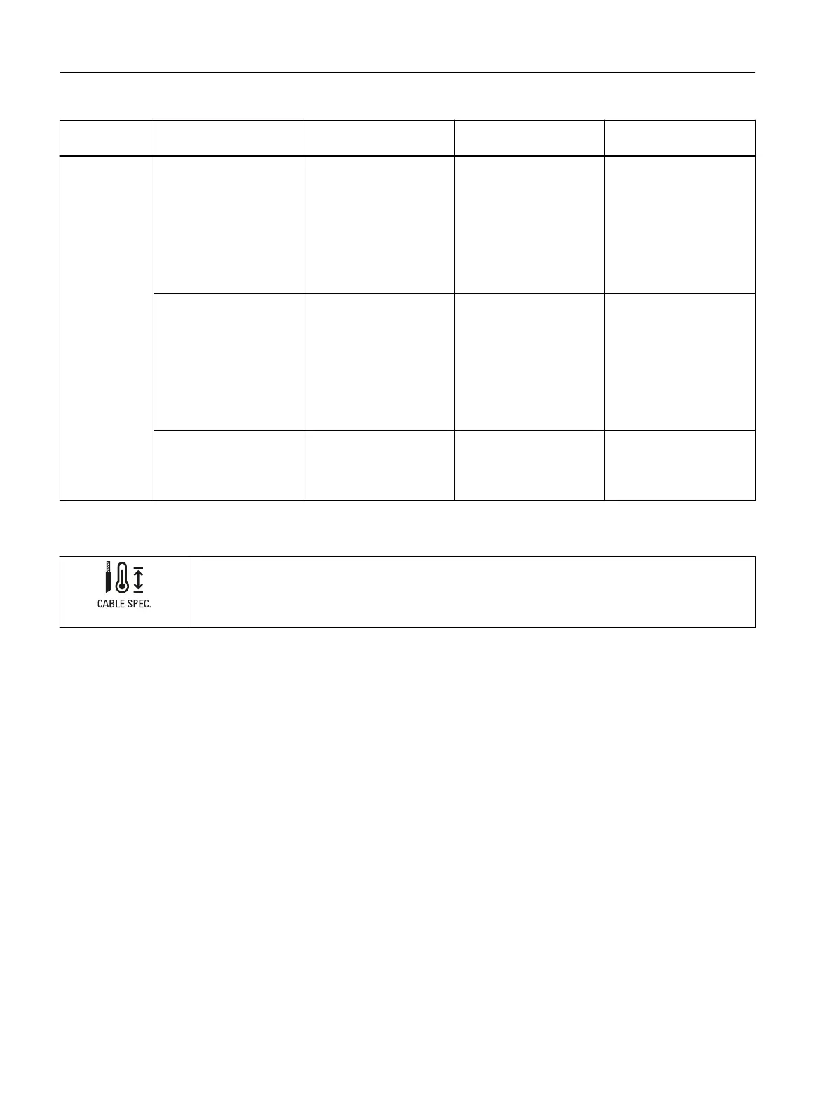
Function Maximum cable length Cable type Cable cross-section
X5060 Logic supply PDC (1L+,
1M)
20m
• <2m unshielded
• ≥2m shielded
Solid and stranded sup‐
ply cable:
AWG*: 20 to 16 or
0.5mm
2
to 1.5mm
2
For through-wiring for
maximum permissible
terminal currents, use
AWG*16 or 1.5mm
2
.
Safe Torque O 20m
• <2m unshielded
• ≥2m shielded
Solid and stranded sup‐
ply cable:
AWG*: 20 to 16 or
0.5mm
2
to 1.5mm
2
For through-wiring for
maximum permissible
terminal currents, use
AWG*16 or 1.5mm
2
.
SSI interface 20m Shielded, one twisted
pair per signal pair
Solid and stranded sup‐
ply cable:
AWG*: 22 to 16 or
0.34mm
2
to 1.5mm
2
* American Wire Gauge
Note that connected mains lines must be designed according to the expected minimum and maximum
ambient temperature.
For the temperature increase at the terminal point, take into account an extra 20 °C as compared to the
ambient temperature.
Installing/removing the connection plug
Installing the connection plug
Insert all plugs into the plug-in connector as far as they will go. In the case of possible
vibration load, fasten the connectors to the PDC with the captive screws.
Removing the connection plug
Loosen the screwed connections of the connectors. Remove the connectors.
Connecting
3.1Terminal assignment
PDC600(F)
22 Equipment Manual, 12/2023, A5E50502703-AB