Table 3-2 Pin assignment: Interface X4060 for supply voltage of inputs/outputs
Pin Designation Function Pin Designation Function
1 2M Reference potential
of supply of inputs/
outputs
2 2M Reference potential
of supply of inputs/
outputs
3 2L+ Supply of inputs/
outputs
4 2L+ Supply of inputs/
outputs
• Pin assignment: Interface X5060 for supply voltage of logic supply of PDC
Table 3-3 Pin assignment: Interface X5060 for supply voltage of logic supply of PDC
Pin Designation Function Pin Designation Function
1 1M Reference potential
of logic supply of PDC
2 1M Reference potential
of logic supply of PDC
3 1L+ Logic supply of PDC 4 1L+ Logic supply of PDC
The logic supply voltages 1L+, 2L+ with associated ground potentials 1M, 2M are electrically isolated from
one another.
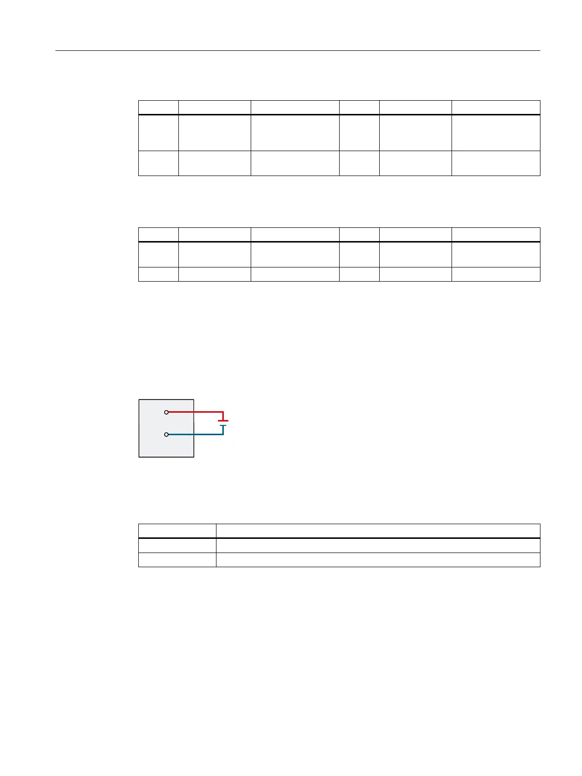
Connection of supply voltage for the power unit (24VDC to 48VDC)
The gure below shows the connection of the 24 V DC to 48 V DC supply voltage for the power
unit to the interface X5050:
Figure3-3 Connection of power unit supply
• Pin assignment: Interface X5050 for power supply of power unit
Table 3-4 Pin assignment: Interface X5050 for supply of power unit
Designation Function
4L+ Power supply of power unit
4M Reference potential of power supply of power unit
Connecting of solid conductors and stranded conductors (stranded wire) with end sleeve
To connect a wire, proceed as follows:
1. Strip 8 to 11mm of insulation from the wires.
2. Crimp the stranded conductors with end sleeves.
3. Insert the wire into the spring-loaded terminal as far as it will go.
Connecting
3.3Connecting the supply voltages
PDC600(F)
Equipment Manual, 12/2023, A5E50502703-AB 25