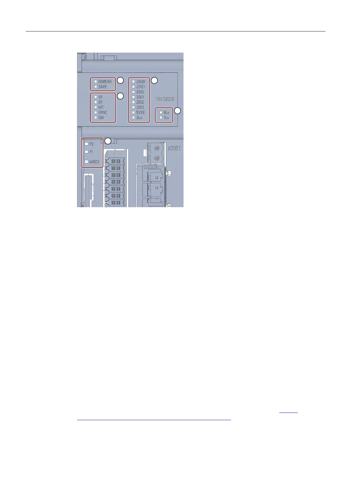
① Diagnostic LEDs for the drive controller:
• RDY/ERR = Drive status
• SAFE = Safety function status
② Diagnostic LEDs for the PROFINET communication:
• SF = PROFINET group error
• BF = PROFINET bus error
• MT = PROFINET maintenance request
• SYNC = PROFINET isochronous mode (IRT)
• ON = PROFINET communication started
③ Diagnostic LEDs for the sensor unit:
• 2DQx/2DIx = Status of digital inputs/outputs
• 5VSE = Output of supply voltage of motor encoder
• 2L+ = Infeed of supply voltage for the sensor unit
④ Diagnostic LEDs for power unit and logic unit:
• 4L+ = Infeed of supply voltage of power unit
• 1L+ = Infeed of supply voltage of logic unit
⑤ Diagnostic LEDs PROFINET ports and service (behind the lower front cover):
• P1/P2 = Status information of PROFINET port
• MRES = Service function status
Figure4-1 LED displays
You can nd detailed information and descriptions for the individual fault and
alarm messages and the meanings of the LEDs for the status of the drive
controller in the System Manual SIMATIC MICRO-DRIVE Drive controller PDC (https://
support.industry.siemens.com/cs/ww/en/view/109774126)
You can nd additional information on the topic of "Interrupts" in the STEP7 online help.
Alarms, diagnostics, error messages and system events
4.1Status and error display
PDC600(F)
32 Equipment Manual, 12/2023, A5E50502703-AB