Introduction
1.2Description
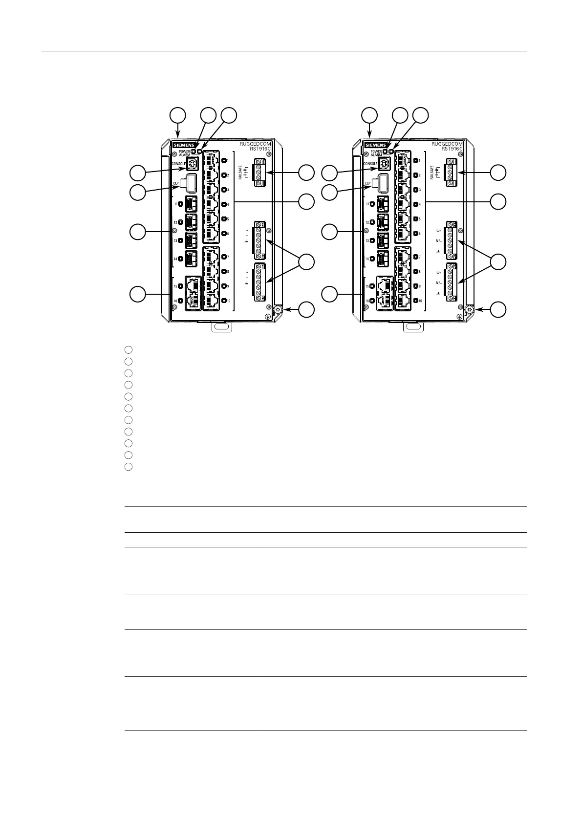
1
LO DC Variant
2
HI AC/DC Variant
3
POWER LED
4
ALARM LED
5
USB Console Port
6
CLP Port
7
SFP Tranceiver Sockets (Ports 11 to 14)
8
Copper Ethernet Ports (Ports 1 to 10, 15, and 16)
9
Failsafe Alarm Relay
10
Power Supply Terminal Block
11
Chassis Ground Screw
Figure1.1 RUGGEDCOM RST916C
POWER LED Illuminates green when power is supplied to the device and after
boot up is complete.
ALARM LED Illuminates red during boot up and when an alarm condition exists.
USB Console Port The USB Type-B console port is for interfacing directly with the
device and accessing initial management functions. For information
about connecting to the device via the serial console port, refer to
"Connecting to the Device" (Page 21).
CLP Port The Configuration License PLUG (CLP) is a removable storage
medium for configuration data and licenses. For more information,
refer to "Inserting/Removing the CLP" (Page 22)
Communication Ports Communication ports in general receive and transmit data, as
well as provide access to the RUGGEDCOM ROS Web interface.
For more information about the various ports available, refer to
"Communication Ports" (Page 25).
Failsafe Alarm Relay Latches to default state when a power disruption or other alarm
condition occurs. For more information, refer to:
• "Connecting the Failsafe Alarm Relay" (Page 13)
• "Failsafe Alarm Relay Specifications" (Page 29)
RUGGEDCOM RST916C
Installation Manual, 04/2023, C79000-G8976-1490-07
3

 Loading...