Installing the Device
2.5.2Wiring Examples
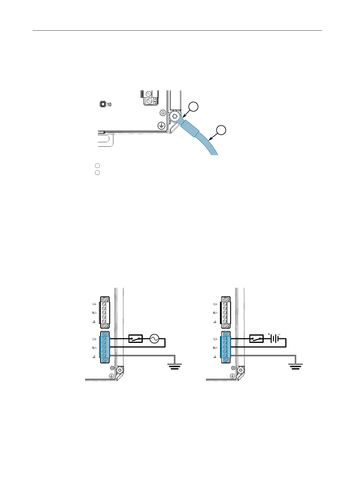
4. Connect the chassis ground screw to ground (Potential Earth). It is
recommended to terminate the ground connection with an M4 ring or spade
lug, and then torque to 1.7 N·m (15 lbf-in).
1
M4 Screw
2
M4 Ring Lug
Figure2.11 Chassis Ground Connection
5. Connect the external power supply to a power source. The Power LED on the
device will turn green when power is being supplied to the device.
2.5.2 Wiring Examples
The following illustrate how to connect single and dual power supplies to the device.
HI Power Supply Configurations
Figure2.12 Single HI AC Power Input
Configuration
Figure2.13 Single HI DC Power Input
Configuration
18
RUGGEDCOM RST916C
Installation Manual, 04/2023, C79000-G8976-1490-07

 Loading...