Installation, wiring, commissioning, removal
3.3 Installing and connecting
CP 443-5 Extended
34 Equipment Manual, 01/2023, C79000-G8976-C162-10
Procedure
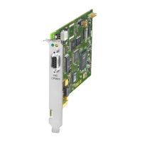
1. Plug in the CP 443-5 Extended
The CP 443-5 Extended can be operated in the following racks:
• Central rack CR2, CR3
• Universal rack UR1 UR2 or UR2H
as central device
as central device with rack no. 1-6 (only possible if there is no DP operation).
The CP 443-5 Extended cannot be used in an ER1 or ER2 expansion rack.
Suitable slots in the rack:
With the exception of the slots reserved for the power supply and IM-R, the CP 443-5
Extended can be inserted in all slots with a P and K bus interface (in the central or in
an expansion rack no. 1-6).
When you are using PROFIBUS
-DP, the module must only be operated in the central rack!
When using the universal rack as an extension rack, you require an IM with a communication
bus link!
2. Connection to PROFIBUS
3. Project engineering Depending on the communication services being used, configuration involves the
following steps:
• Node initialization
This is necessary in all cases. This assigns a PROFIBUS address and bus parameters
to the PROFIBUS CP.
• Connection configuration
This is necessary when using the communications services, S7 functions and FDL
connections (SEND/RECEIVE interface).
• DP configuration
This is necessary when the DP mode is used.
For details, refer to /1/ (Page 49).
configuration
You can connect the PG as follows via the PROFIBUS interface of the CP when
configuring the CP:
• via LAN / PROFIBUS
Requirement: The CP 443-5 Extended must already have a PROFIBUS address.
As an alternative, configuration via the CPU and its available interfaces to the PG/PC is
also possible.
For details, refer to /1/ (Page 49).

 Loading...